Emergency lamp
A technology of emergency lights and chargers, applied in the field of emergency lights, can solve the problems of large charging loss, large internal resistance, and limited charge and discharge times, and achieve the effects of short charging time, enhanced practicability, and low charging loss
- Summary
- Abstract
- Description
- Claims
- Application Information
AI Technical Summary
Problems solved by technology
Method used
Image

Examples
Embodiment 1
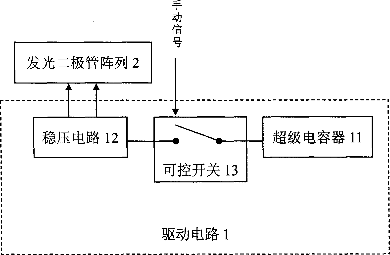
[0028] Embodiment one, such as figure 1 As shown, an emergency light includes a driving circuit 1 and a light-emitting element 2. The driving circuit 1 includes a supercapacitor 11, a controllable switch 13 and a voltage stabilizing circuit 12, and the supercapacitor 11 and the stabilizing circuit 12 can be connected in series. The control switch 13 is connected to the light-emitting element 2 at the output end of the voltage stabilizing circuit 12, and the supercapacitor is used as an energy storage element to store electric energy. The supercapacitor 11 drives the light-emitting element 2 to emit light through the voltage stabilizing circuit 12.
[0029] The light emitting element 2 is an array of light emitting diodes. The light-emitting diodes can be divided into multiple groups, which is convenient to adjust the brightness by connecting the number of groups; the brightness can also be adjusted by changing the driving current, but the efficiency is low.
[0030] The contr...
Embodiment 2
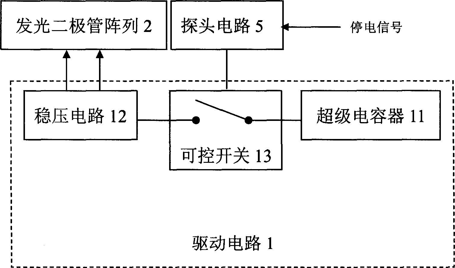
[0032] Embodiment two, such as figure 2 As shown, the difference from Embodiment 1 is that it also includes a probe circuit 5, the probe circuit 5 is connected to the controllable switch 13, the brightness detection signal output by the probe circuit 5 controls the controllable switch 13, and the probe circuit 14 receives When there is a power failure signal, or when it is detected that the brightness is lower than the set value and needs to be illuminated, the controllable switch 13 is connected, and the emergency light works.
Embodiment 3
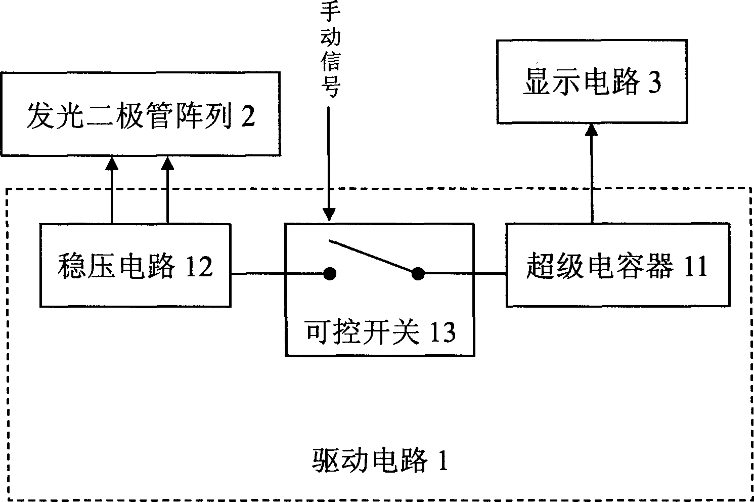
[0033] Embodiment three, such as image 3 As shown, the difference from Embodiment 1 is that it further includes a display circuit 3 connected to the supercapacitor 11, and displays the charge of the supercapacitor 11 through voltage sampling. Since the voltage of the supercapacitor decreases linearly during use, the display circuit 3 can reflect the charge of the supercapacitor in real time, which is convenient for controlling whether the emergency light needs to be charged.
PUM
 Abstract
Description
Claims
Application Information
 - R&D
- Intellectual Property
- Life Sciences
- Materials
- Tech Scout
- Unparalleled Data Quality
- Higher Quality Content
- 60% Fewer Hallucinations
Browse by: Latest US Patents, China's latest patents, Technical Efficacy Thesaurus, Application Domain, Technology Topic, Popular Technical Reports.
© 2025 PatSnap. All rights reserved.Legal|Privacy policy|Modern Slavery Act Transparency Statement|Sitemap|About US| Contact US: help@patsnap.com