Method and device for forming wave windings for rotor and stator cores of electric machines

A technology of wave winding and stator lamination, which is applied in the direction of electric components, manufacturing motor generators, prefabricated windings embedded in motors, etc., and can solve problems such as difficult deformation and poor deformation

Inactive Publication Date: 2006-08-02
ELMOTEC STATOMAT VERTRIEBS
View PDF5 Cites 14 Cited by
  • Summary
  • Abstract
  • Description
  • Claims
  • Application Information

AI Technical Summary

Problems solved by technology

The difficulty in manufacturing such stators is that the thick rectangular wires (whose width is equal to the slot width) can only be deformed with difficulty in conventional winding and drawing methods and generally protrude beyond the winding ends of the stator laminations at the end faces Due to the many overlapping windings on the circumference and the poor deformability of the winding wires, a too large radius width is practically difficult to reduce by conventional winding end forming dies

Method used


Image

  • Method and device for forming wave windings for rotor and stator cores of electric machines
  • Method and device for forming wave windings for rotor and stator cores of electric machines
  • Method and device for forming wave windings for rotor and stator cores of electric machines

Examples


Embodiment Construction

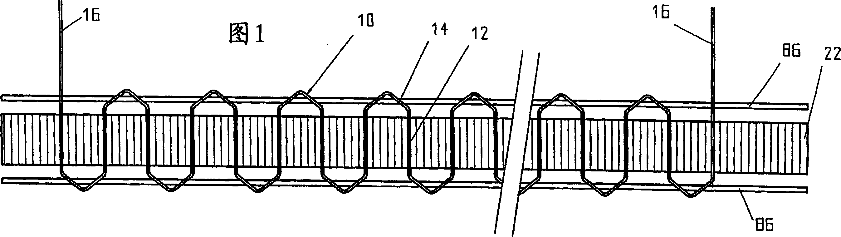
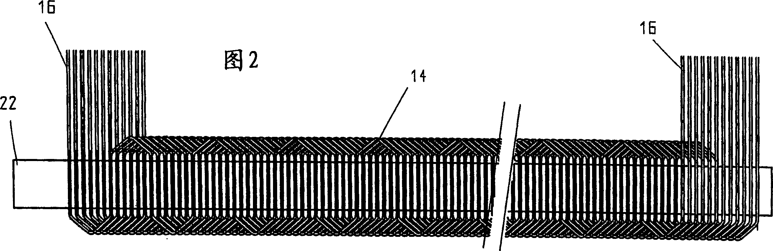
[0023] The wave winding 10 shown in FIG. 1 has a certain number of waves depending on the number and arrangement of the slots of the rotor or stator laminations to be equipped with the winding, which consist of parallel connecting sections 12 and pointed winding ends 14 . The connection terminal of the wave winding is indicated by 16 . In the example shown, every sixth slot of a stator lamination stack is occupied by the wave winding 10 shown, wherein the connecting section 12 extends through the stator slot and the peak-shaped winding head 14 emerges from the stator lamination at the end face stand out from the group. In the present exemplary embodiment, five stator slots are respectively freed between two stator slots occupied by wave windings 10 , into which other wave windings 10 of this type are inserted. A total of eight layers, here conductor layers in a groove 18, can be present, for example in Figure 10 In the rectangular, radially inwardly open slots 18 of a stat...


PUM


Abstract

The invention relates to a method which is used to shape and guide a wave winding (10) with a connecting section (12) which is connected through a winding end portion (14) into a rotor plate assembly or a stator-plate assembly (20) of a motor, wherein the method comprises: cutting a wave winding belt (52) which is composed of winding wires (56) whose lateral sections take rectangle shapes or circular shapes and are shaped continuously into wave windings (10) which are respectively provided with a certain number of waveforms, alternately encircling the winding wires around the lateral surface of a shaped protuberance (50) on the periphery of a shaped element which can be rotatably driven though a wire guiding device in a shaping process to lay, then, guiding the wave windings (10) which is cut by the wave winding belt (52) into the rotor plate assembly or the stator-plate assembly or a groove (89) which is radially opened outwards of a transferring tool (88) which is similar to a rotor, and transferring from the groove (89) of the transferring tool (88) which is similar to the rotor to the groove which is radially opened inwards of the rotor plate assembly or the stator-plate assembly. The invention is characterized in that the winding wires encircle on the periphery of two discs (46, 48) which are rotatably driven in parallel axially according to one line respectively or on the lateral surface of the shaped protuberance (50) which are cross-arranged on the periphery of the roller which is driven rotatably according to two lines, wherein the distance between the shaped protuberance (50) on a line and the shaped protuberance on next line can be enlarged like this in an angular range that the wave winding belt (52) is driven on the periphery of the discs (46, 48) and the roller, which enables the lateral surface of the shaped protuberance (50) shapes the winding end portion (14) of the wave winding (10).

Description

technical field [0001] The invention relates to a method and a device for forming and introducing wave windings with connection sections connected by winding ends into rotor and stator laminations of electric machines, in which winding wires with rectangular or circular cross-section The formed continuously formed wave winding strip is cut into wave windings each having a certain number of waves, and the winding wire is alternately surrounded by a wire guide during the forming process around the forming protrusions arranged on the circumference of a rotatably driven forming element laying on the outer side, and then guide the wave winding cut from the wave winding strip into the radially outwardly open slots of a rotor or stator lamination stack or of a rotor-like transfer tool and, if necessary, from a rotor-like The slots of the transfer tool are displaced into radially inwardly open slots of a rotor or stator laminated core. Background technique [0002] For example from...

Claims


Application Information

Patent Timeline
Patent Type & Authority Applications(China)
IPC IPC(8): H02K15/04H02K15/06
CPCY10T29/49012H02K15/06Y10T29/49009Y10T29/49071Y10T29/49073H02K15/0478H02K15/04
Inventor S·萨迪库
Owner ELMOTEC STATOMAT VERTRIEBS
Why Eureka
Try Eureka