Sintered heat pipe and its manufacturing method

A manufacturing method and sintering technology, used in indirect heat exchangers, lighting and heating equipment, etc., can solve the problems of large capillary force and small liquid backflow resistance, and achieve the effect of strong capillary force

Inactive Publication Date: 2006-08-09
FU ZHUN PRECISION IND SHENZHEN +1
View PDF0 Cites 17 Cited by
  • Summary
  • Abstract
  • Description
  • Claims
  • Application Information

AI Technical Summary

Problems solved by technology

Therefore, the single capillary structure of this structure cannot take into account the large capillary force and small liquid return resistance at the same time.

Method used


Image

  • Sintered heat pipe and its manufacturing method
  • Sintered heat pipe and its manufacturing method
  • Sintered heat pipe and its manufacturing method

Examples


Embodiment Construction

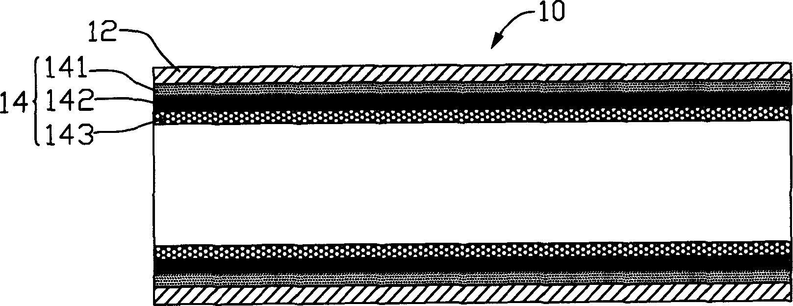
[0012] figure 1 This is a schematic diagram of the axial cross-section of the first embodiment of the sintered heat pipe of the present invention. The sintered heat pipe 10 includes a metal shell 12, and a multilayer capillary structure 14 composed of sintered powder particles is formed on the inner wall of the shell 12. The particles can be ceramic powder particles, or metal powder particles such as copper powder, etc. The multilayer capillary structure 14 is stacked on top of each other along the radial direction of the housing 12. The figure shows three layers, that is, along the inner wall of the housing 12 outwards. It is the inner layer 141, the middle layer 142 and the outer layer 143 in sequence. The particle sizes used between the layers are all different from each other and are arranged in order of increasing from the inner wall of the housing 12 to the axial direction. The powder particle size is the smallest, the middle layer 142 takes the second place, and the outer...


PUM


Abstract

Present invention discloses a sintering type heat tube and manufacturing method. Said method includes 1, providing a metallic shell and at least three kinds of metal powder with different particle size, 2, in turn filling above-mentioned metal powder in particle size scaling up or degressive sequence, each time using a cored bar as structure layer thickness control and rapid sintering,3, whole sintering after all metal powder filling-in, pulling out cored bar after completing sintering, 4, filling working fluid in shell cavity and enclosing said shell, to obtain sintering type heat tube with mutually complicated multiwall capillary structure in inner wall and distributed according to particle size scaling up or degressive sequence.

Description

【Technical Field】 [0001] The present invention relates to a heat transfer device and a manufacturing method thereof, in particular to a sintered heat pipe using capillary principle for heat transfer and a manufacturing method thereof. 【Background technique】 [0002] In the current field of heat dissipation, heat pipes are widely used due to their fast heat transfer characteristics. They use the principle that the working liquid in the shell absorbs or releases a large amount of heat during the gas-liquid two-phase transformation. It is provided with a capillary structure that facilitates the reflux of the condensed liquid. Its function is to provide the driving force required to accelerate the reflux of the condensed liquid. The driving force comes from the pressure difference generated by capillary action. Commonly used capillary structures are groove-shaped and wire mesh-shaped. Or sintered metal powder, etc. When in use, one end of the heat pipe (evaporating end) is placed at ...

Claims


Application Information

Patent Timeline
Patent Type & Authority Applications(China)
IPC IPC(8): F28D15/04
Inventor 吴荣源洪居万骆长定郑景太
Owner FU ZHUN PRECISION IND SHENZHEN
Why Eureka
Try Eureka