Multifunction chip-detecting apparatus

A chip detection, multi-functional technology, applied in measurement devices, material analysis by optical means, instruments, etc., can solve problems such as single function, and achieve the effect of flexible use, wide wavelength range, and wide application range

Inactive Publication Date: 2006-08-09
DONGHUA UNIV
View PDF0 Cites 12 Cited by
  • Summary
  • Abstract
  • Description
  • Claims
  • Application Information

AI Technical Summary

Problems solved by technology

[0006] The instruments with the above functions only have a single function. In order to real...

Method used


Image

  • Multifunction chip-detecting apparatus
  • Multifunction chip-detecting apparatus
  • Multifunction chip-detecting apparatus

Examples


Embodiment Construction

[0046] The present invention will be further described below in conjunction with accompanying drawings, but the protection scope of the present invention should not be limited thereby.

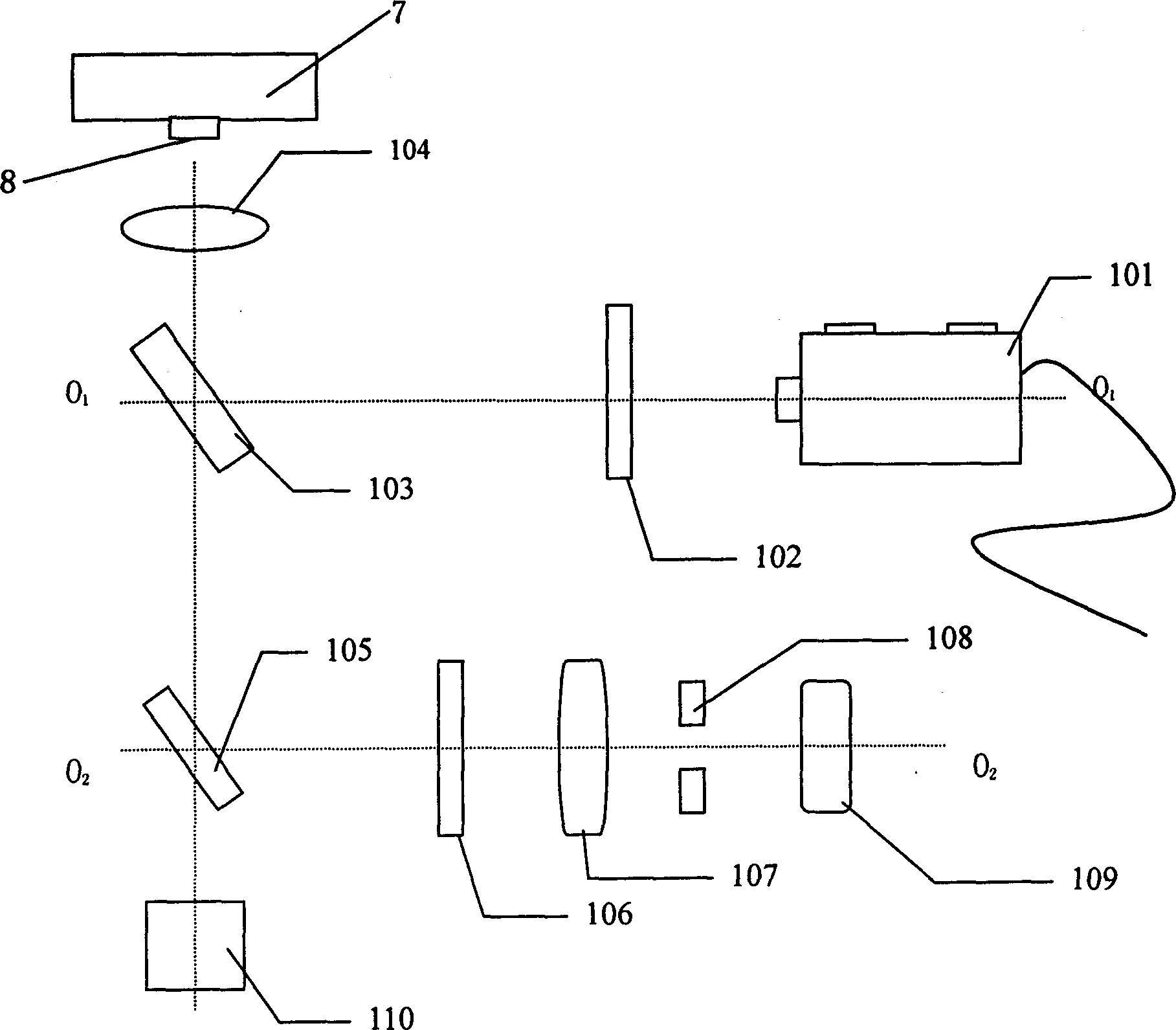
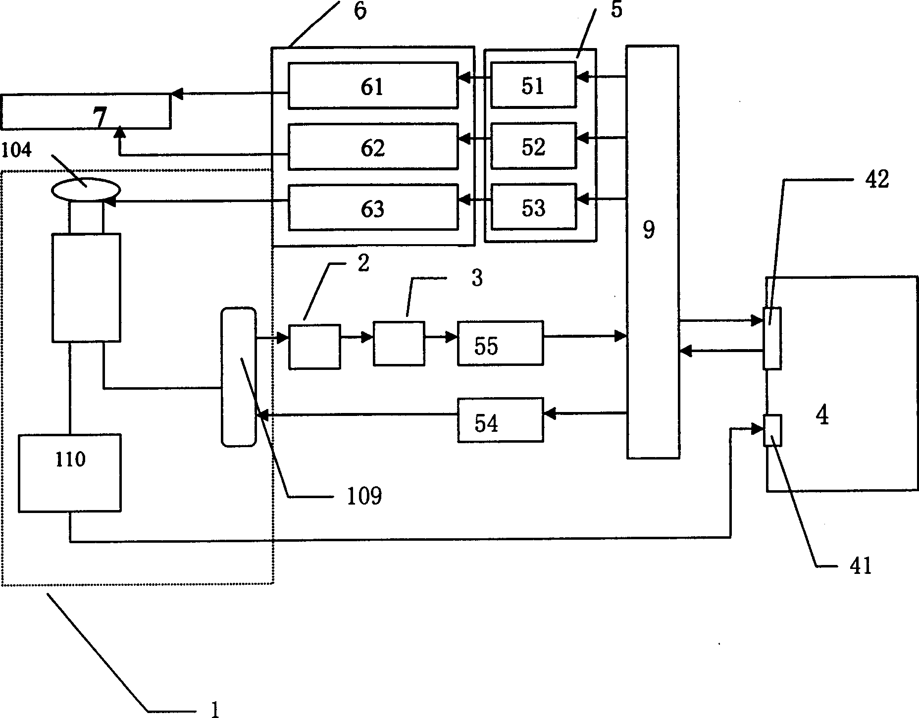
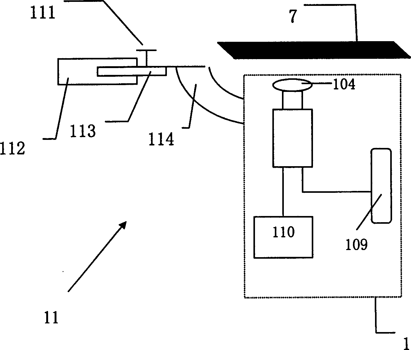
[0047] Such as Figure 1 to Figure 3 Shown, the present invention is a kind of multifunctional chip detection device, and its composition comprises:

[0048] A frame and a chip platform 7 also include:

[0049] ① Detection optical path module 1 (such as figure 1 Shown) is a template for fixedly setting the detection optical path, and its optical path is constituted as follows: a light source 101, the first optical filter 102 and the half mirror 103 are sequentially arranged on the same optical axis along the advancing direction of the light beam sent by the light source 101 , the half-mirror 103 is placed at 45° with the above-mentioned light beam, the direction of the light beam reflected by the half-mirror 103 is the objective lens group 104, and the light beam passing through the objectiv...


PUM


Abstract

Multifunction chip inspection unit includes one frame, platform for holding chip, light path detecting module, light path inversion mechanism and control interface system. Said detecting light path in photoelectric detection module is located above chip platform, when reflection mirror of light path switch is in light path, array chip co-focusing scanning, miniflow control chip laser-induced fluorescence, and array chip CCD scanning can be completed. Said invention has wide applicability, flexible detecting light path regulation and data processing completed by computer.

Description

technical field [0001] The invention relates to biochips for life sciences, medicine, and analytical chemistry, in particular to a multifunctional chip detection device, which is equipped with three types of microfluidic chip laser-induced fluorescence detection, array chip laser confocal scanning, and array chip CCD scanning. Features. Background technique [0002] Biochip is a product with great characteristics of the times in the high-tech field in recent years, and belongs to the comprehensive interdisciplinary field of molecular biology, physics and microelectronics. Biochips are widely used in life sciences, medicine, environmental monitoring, food industry, scientific research, biosensors and other fields, and integrate various biochemical reaction processes in these fields to realize the detection of biological macromolecules, proteins, microorganisms, etc. Efficient and fast testing and analysis of biologically active substances. [0003] Laser-induced fluorescenc...

Claims


Application Information

Patent Timeline
IPC IPC(8): G01N21/00G01N21/64G01N21/84
Inventor 李汪根丁永生
Owner DONGHUA UNIV
Why Eureka
Try Eureka