Ultraviolet irradiation apparatus and optical device manufacturing apparatus

A technology of an illumination device and an optical device, which is applied in the direction of optics, optical components, and image reproducers using projection devices, can solve the problems of inability to improve convenience, inability to miniaturize light sources, and poor operability, and achieve Effects of lower power consumption, prevention of thermal deterioration, and improved convenience

Inactive Publication Date: 2006-08-16
SEIKO EPSON CORP
View PDF1 Cites 0 Cited by
  • Summary
  • Abstract
  • Description
  • Claims
  • Application Information

AI Technical Summary

Problems solved by technology

[0008] However, since the above-mentioned ultraviolet irradiation device uses a mercury lamp as a light source that emits a light beam in the ultraviolet region, it is not possible to reduce the size of the light source itself due to restrictions on the shape of the discharge luminous tube and the reflector.
In addition, since an optical fiber is used in addition to the above-mentioned light source, the size of the ultraviolet irradiation device is increased.
[0009] In addition, in the above-mentioned ultraviolet irradiation device, it is necessary to lead the front end portion of the optical fiber used to emit the light guide beam to the fixed position of the cross dichroic prism and the liquid crystal panel, which has poor operability and cannot provide convenience. improve

Method used


Image

  • Ultraviolet irradiation apparatus and optical device manufacturing apparatus
  • Ultraviolet irradiation apparatus and optical device manufacturing apparatus
  • Ultraviolet irradiation apparatus and optical device manufacturing apparatus

Examples


no. 1 Embodiment approach

[0058] Next, a first embodiment of the present invention will be described with reference to the drawings.

[0059] 1. The structure of the projector

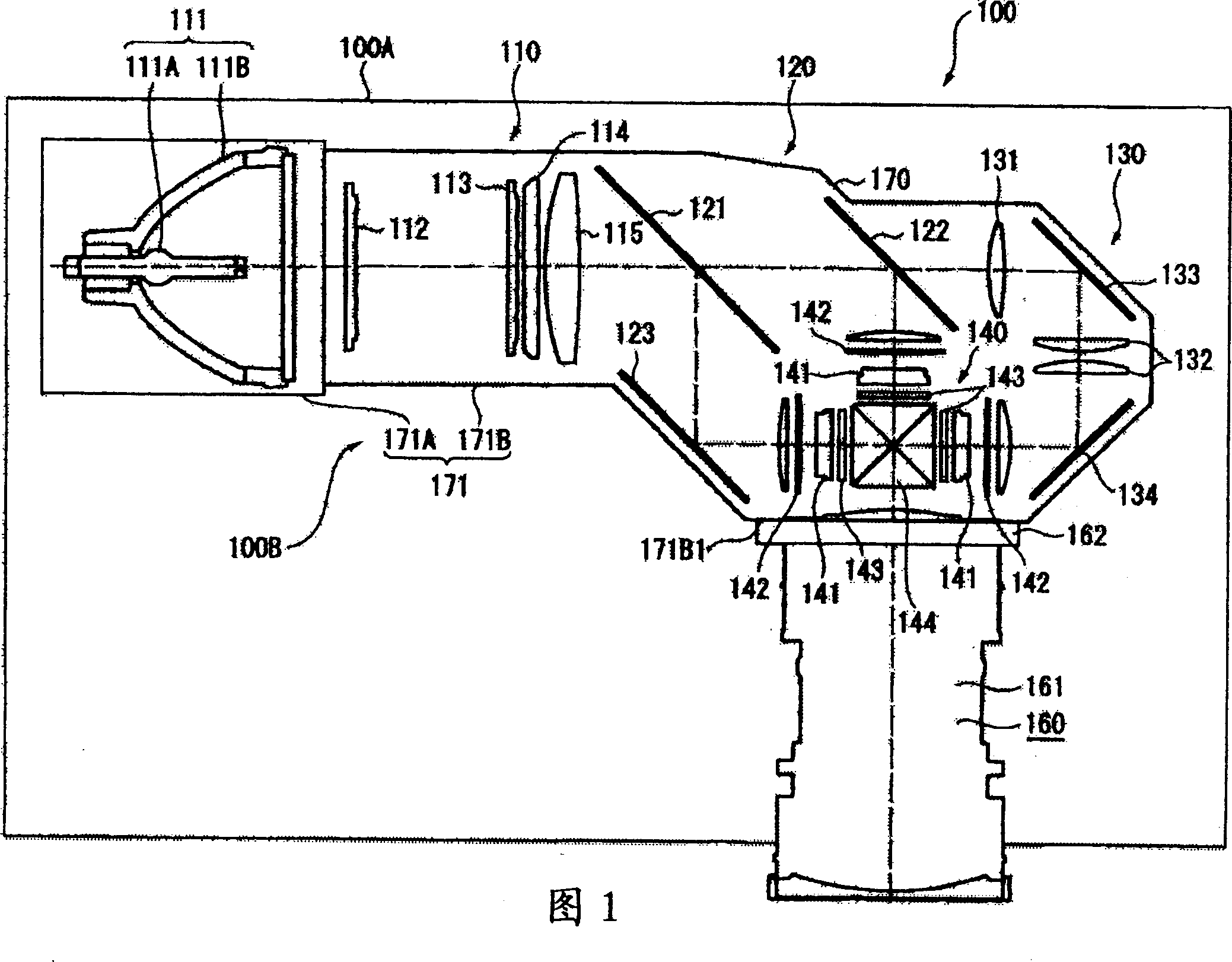
[0060] FIG. 1 schematically shows the configuration of a projector 100 including an optical device to be manufactured in the first embodiment.

[0061] The projector 100 is used to form a color image by modulating light beams emitted from a light source according to image information, and enlarge and project the formed color image onto a screen not shown. As shown in FIG. 1 , this projector 100 includes an exterior housing 100A and an optical unit 100B.

[0062] In addition, although illustration is omitted in FIG. 1 , in the space other than the optical unit 100B inside the exterior housing 100A, a power supply unit for supplying external power to the components of the projector 100 is arranged. ; a cooling assembly, used to cool the inside of the projector 100; and a control substrate, used to control the projector 100 as a...

no. 2 Embodiment approach

[0285] Next, a second embodiment of the present invention will be described. In the following description, the same reference numerals are assigned to the same parts as those already described, and description thereof will be omitted.

[0286] Figure 27 It is a perspective view showing the structure of the second irradiation device 82' in the second embodiment.

[0287] In this embodiment, if Figure 27 As shown, the difference from the above-mentioned first embodiment is that a plurality of irradiation device main bodies are arranged in advance in the plurality of through-holes 822D1 of the support plate 822D of the second irradiation device 82 described in the above-mentioned first embodiment. 821. In addition, according to this configuration, the control of the plurality of irradiation device main bodies 821 by the control unit 93 is also different from the first embodiment described above.

[0288] In the memory 933 of the control unit 93, the following data are inclu...


PUM


Abstract

To provide an ultraviolet ray irradiation device which is miniaturized and improved in convenience. The fixed device (3) functioning as the ultraviolet ray irradiation device is equipped with: an irradiation device main body (811) having a self light emitting element for emitting luminous flux in an ultraviolet region, a light condensing element for condensing the luminous flux and disposed on the luminous flux emitting side of the self light emitting element, and a fixed member made of metal which connects the self light emitting element to the light condensing element and is connected to the self light emitting element so that heat can be transmitted; and a moving mechanism (812) supporting the irradiation device main body (811) and moving the irradiation device main body in a direction where it approaches to or separates from an object to be irradiated.

Description

technical field [0001] The present invention relates to an ultraviolet irradiation device and a manufacturing device of an optical device. Background technique [0002] In the past, a projector equipped with an optical device and a projection optical device (projection lens) has been known. The optical device is equipped with three light modulating devices (liquid crystal panels) for adjusting R, G, and B signals according to image information for each color light. Modulate the 3 kinds of colored light; and the color synthesis optical device (cross dichroic prism), these light modulation devices are installed, used to synthesize the modulated 3 kinds of light beams and form image light; the projection optical device is used for the formed The image light is magnified and projected. [0003] As far as this kind of projector is concerned, in order to obtain a clear image, each liquid crystal panel must be on the back focus position of the projection lens. In addition, in ord...

Claims


Application Information

Patent Timeline
Patent Type & Authority Applications(China)
IPC IPC(8): G02B27/62G02B27/10H04N9/31
CPCH04N9/3197G02B27/62G02B27/1046G02B27/149H04N9/317H04N9/3105G02B27/1073G02B27/145
Inventor 北林雅志
Owner SEIKO EPSON CORP
Why Eureka
Try Eureka