Microcomputer protector of current mutual inductor

A current transformer and protection device technology, which is applied in the field of protection devices for circuit facilities, can solve the problem that the protection principle of current transformer protection devices has not been greatly developed and innovated.

Active Publication Date: 2006-08-16
江苏能建机电实业集团有限公司
View PDF0 Cites 14 Cited by
  • Summary
  • Abstract
  • Description
  • Claims
  • Application Information

AI Technical Summary

Problems solved by technology

[0008] In a word, the applicant feels in the in-depth research that the protection principle of the current transformer protect

Method used


Image

  • Microcomputer protector of current mutual inductor
  • Microcomputer protector of current mutual inductor
  • Microcomputer protector of current mutual inductor

Examples


Embodiment 1

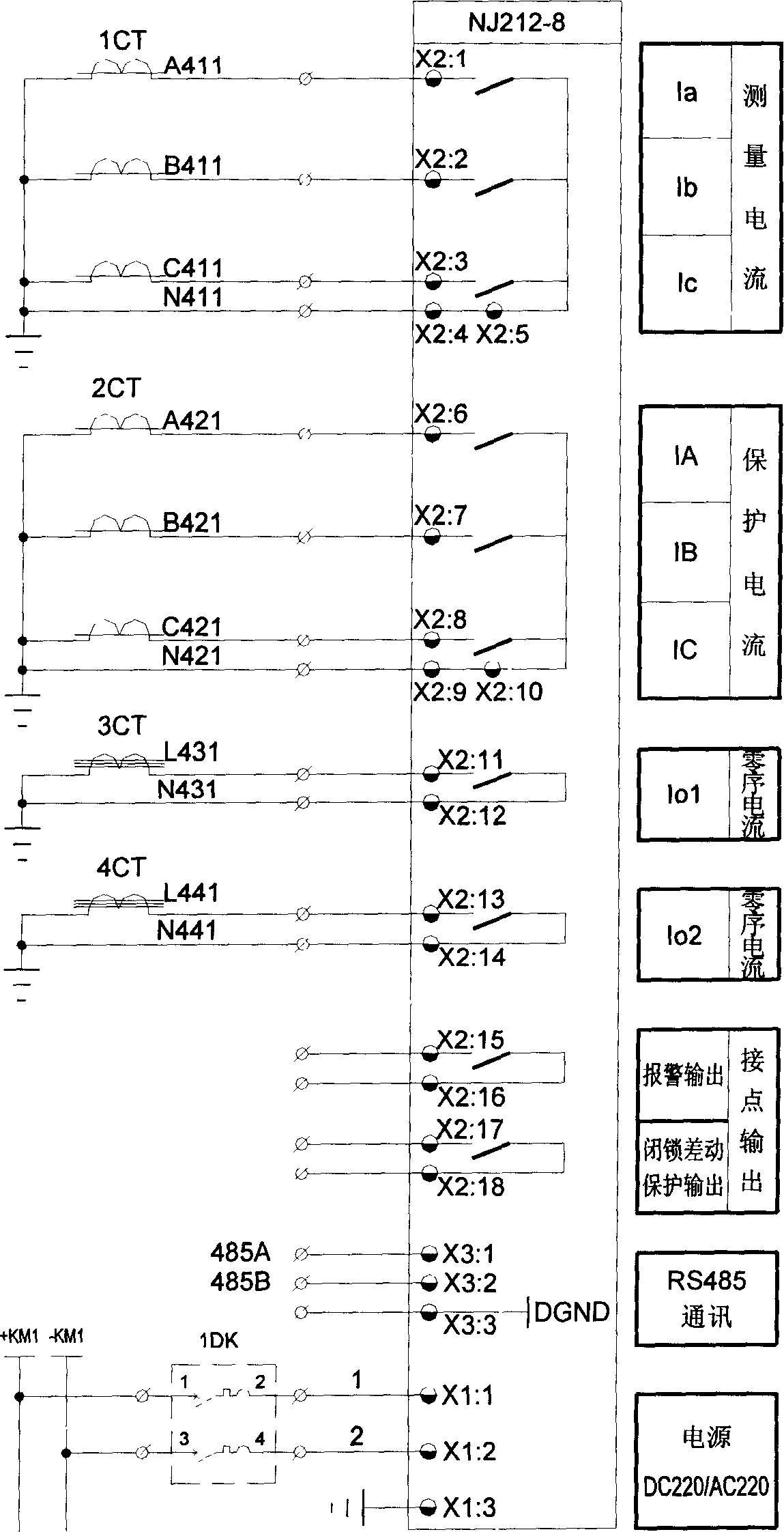
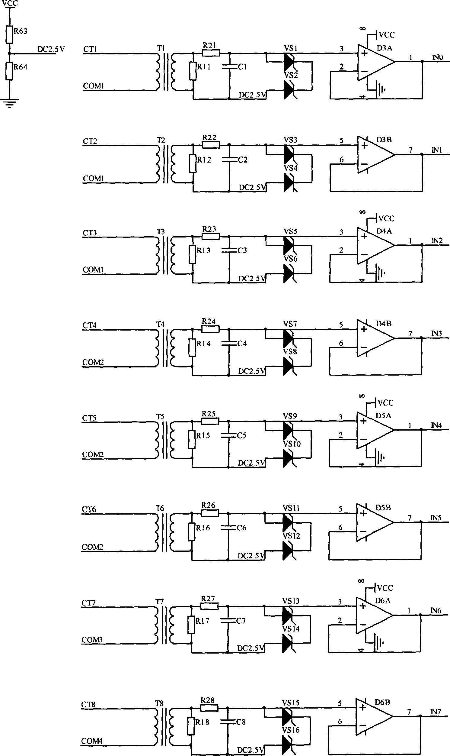
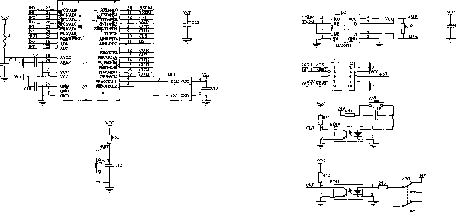
[0027] The microcomputer-based current transformer protection device of this embodiment mainly figure 2 Analog quantity acquisition circuit, image 3 Central processing circuit, Figure 4 Relay output circuit, Figure 5 Power supply circuit, and Figure 6 The external interface and display circuit constitute. Its external wiring such as figure 1 As shown, 1CT-4CT is an external high-voltage current transformer (CT for short), of which 3CT and 4CT are separate input circuits, which can be used to connect zero-sequence current. +KM1 and -KM1 are direct current, which is taken from the direct current bus (the power supply of this equipment can be used for DC220V or AC220V, and DC220V is generally used in the power system). 1DK is a small DC air switch. X2:1——X2:5, X2:6——X2:10, X2:11——X2:12, X2:13——X2:14 are the four sets of signal contacts of the protection device, the particularity of which is the input and Output through contact. Among them, X2:1——X2:5, X2:6——X2:10 each correspond...


PUM


Abstract

The invention consists of an analog quantity collecting circuit, a central process circuit, a relay output circuit, an external port and a display circuit. Wherein, the analog quantity collecting circuit comprises a primary side external current transformer, a voltage transformer whose two ends at secondary side is connected to a sampling resistor, a low-pass filter circuit passing by voltage of sampling resistor, and an positive input end of operational amplifier. The operational amplifier adopts voltage tracing method, and its output is connected to the AD input of CPU in central processing circuit. The output of switching value of CPU is connected to the controlled end of short circuit relay at primary side through photoelectrical coupler.

Description

Technical field [0001] The invention relates to a protection device for a circuit facility, in particular to a protection device for a current transformer. Background technique [0002] Modern power systems have increasingly higher requirements for automation, especially automatic measurement and automatic control. According to the applicant's understanding, current transformers and voltage transformers are widely used in existing power systems to control current, voltage, and frequency (which can be measured by collecting AC voltage). [0003] Generally, the protection of voltage transformers can be realized by leakage switches or air circuit breakers, which is relatively simple, while the protection of current transformers has not seen development for a long time. In fact, the open circuit of the current transformer is more serious than the short circuit of the voltage transformer. A short-circuit of the voltage transformer will burn itself at best, and an open current transfor...

Claims


Application Information

Patent Timeline
IPC IPC(8): H02H7/22H02H7/00
Inventor 许海洋郭余庆
Owner 江苏能建机电实业集团有限公司
Why Eureka
Try Eureka