
Wave-length controlling circuit of light communication wavelength division multiplexing

A technology of wavelength control and wavelength division multiplexer, which is applied in the direction of wavelength division multiplexing system, etc., can solve the problems of being unable to enter commercial use, and achieve the effect of reasonable structure and lines

Inactive Publication Date: 2006-08-16
北京天宇中视科技有限公司
View PDF0 Cites 2 Cited by
  • Summary
  • Abstract
  • Description
  • Claims
  • Application Information

AI Technical Summary

Problems solved by technology

Usually, an optical network needs to use 4 to 6 lasers that can be tuned throughout the network, but such tunable lasers are not yet available for commercial use.

Method used


Image

  • Wave-length controlling circuit of light communication wavelength division multiplexing

Examples


Embodiment Construction

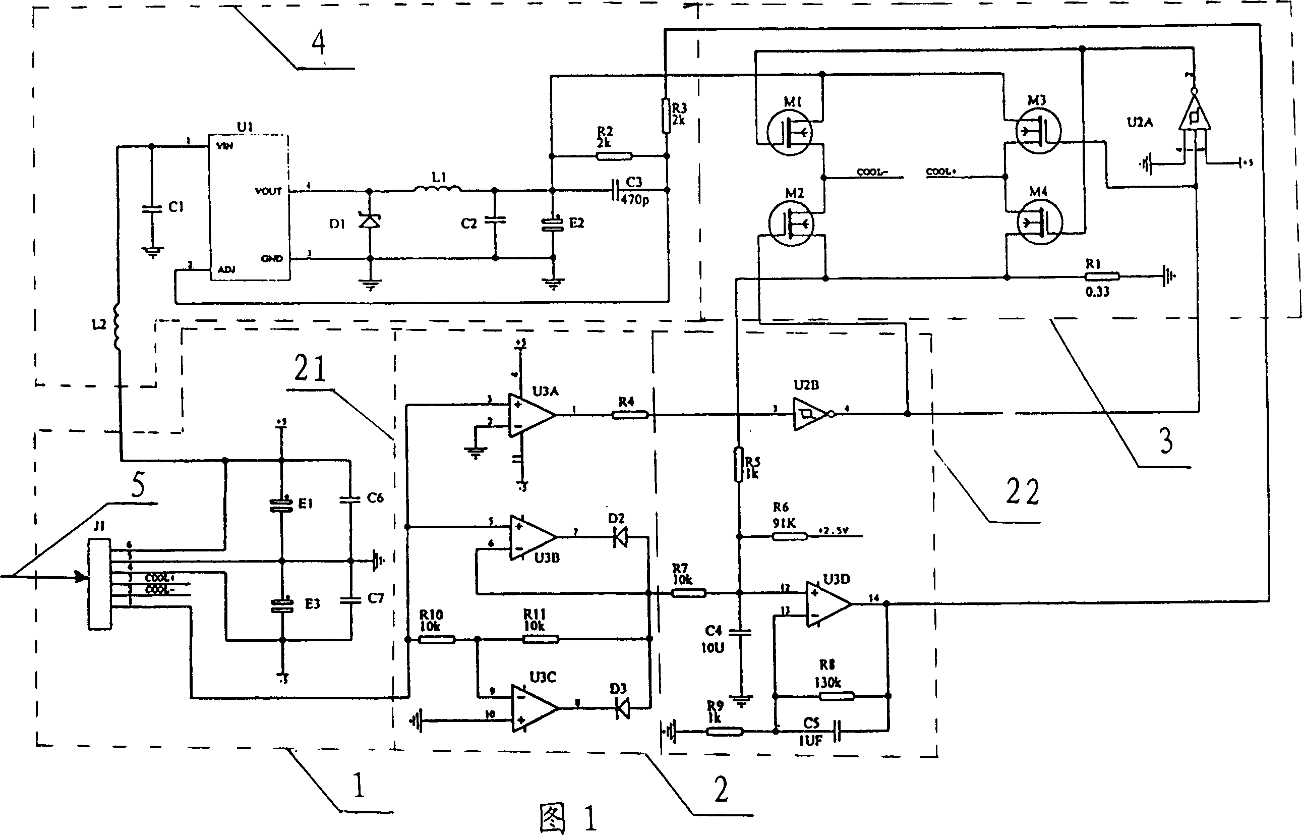
[0027] As shown in Figure 1: a wavelength control circuit in an optical communication wavelength division multiplexing device, including an optical transmitter / receiver 1, a wavelength division multiplexer 2, an optical amplifier 3, an optical monitoring channel 5 and an optical fiber 5 module.

[0028] See Figure 1, E 1 ,E 3 serial connection, C 6 、C 7 After serial connection, the two are connected in parallel, and connected with J 1 Connected in series to form an optical transmitter / receiver 1, U 3A , R 4 in series with U 2B Series, U 3B 、D 2 Series, U 3C 、D 3 in series and with R 10 , R 11 A filter circuit is formed in parallel with the R 5 , R 6 , R 7 、C 4 , U 3D , R 8 , R 9 、C 5 The switching circuits formed are connected in series to form the wavelength division multiplexer 2, and R 1 , U 2A , M 1 , M 2, M 3 , M 4 The input end of the amplifier 3 that constitutes is connected with the output end of this wavelength division multiplexer, by R 2 ,...


PUM


Abstract

The invention includes an optical transceiver, a wavelength division multiplexer, an optical amplifier, an optical monitoring channel and optical fiber. E1, and E3 are connected in series, and C6 and C7 firstly are connected in series, and then in parallel, and are connected to J1 in series to build optical transceiver. U3A, R4 are connected in series, and then are connected to U2B in series. U3B and D2 are connected in series. U3C and D3 are connected in series, and are connected to R10 and R11 in parallel to build a filter circuit, and are connected in series to a switch circuit composed of R5, R6, R7, C4, U3D, R8, R9, and C5. R1, U2A, M1, M2, M3, and M4 compose the input end of amplifier and are connected to the input end of wavelength division multiplexer. The optical fiber control channel composed of R2, R3, C3, E2, L1, L2, C2, U1, and D1 is connected to the output end of amplifier.

Description

Technical field: [0001] The invention relates to a control circuit of optical communication waves, in particular to a wavelength control circuit in optical communication wavelength division multiplexing equipment. Background technique: [0002] Wavelength division multiplexing (WDM) is to combine two or more optical carrier signals of different wavelengths (carrying various information) at the sending end through a multiplexer (also known as a multiplexer, Multiplexer) and couple them to the optical The technology of transmitting in the same optical fiber of the line; at the receiving end, the optical carriers of various wavelengths are separated by a demultiplexer (also known as a demultiplexer or demultiplexer, Demultiplexer), and then the optical receiver is used as a further processing to recover the original signal. This technology of simultaneously transmitting two or more optical signals of different wavelengths in the same optical fiber is called wavelength division...

Claims


Application Information

Patent Timeline
IPC IPC(8): H04J14/02
Inventor 陈海周权
Owner 北京天宇中视科技有限公司
Learn More