Friction damper, especially for washing machines with a rotating drum

A drum washing machine and buffer technology, which is applied to other washing machines, friction shock absorbers, applications, etc., can solve problems such as the complexity of buffer assembly, achieve the effects of reducing pressure, reducing the number of parts, and reducing assembly costs

Inactive Publication Date: 2006-08-16
SUSPA
View PDF2 Cites 2 Cited by
  • Summary
  • Abstract
  • Description
  • Claims
  • Application Information

AI Technical Summary

Problems solved by technology

[0004] A disadvantage of the prior art is that, on the one hand, there are a large number of different and sometimes also very complex parts, and that the assembly of the buffer is complicated, which leads to corresponding manufacturing costs

Method used


Image

  • Friction damper, especially for washing machines with a rotating drum
  • Friction damper, especially for washing machines with a rotating drum
  • Friction damper, especially for washing machines with a rotating drum

Examples


Embodiment Construction

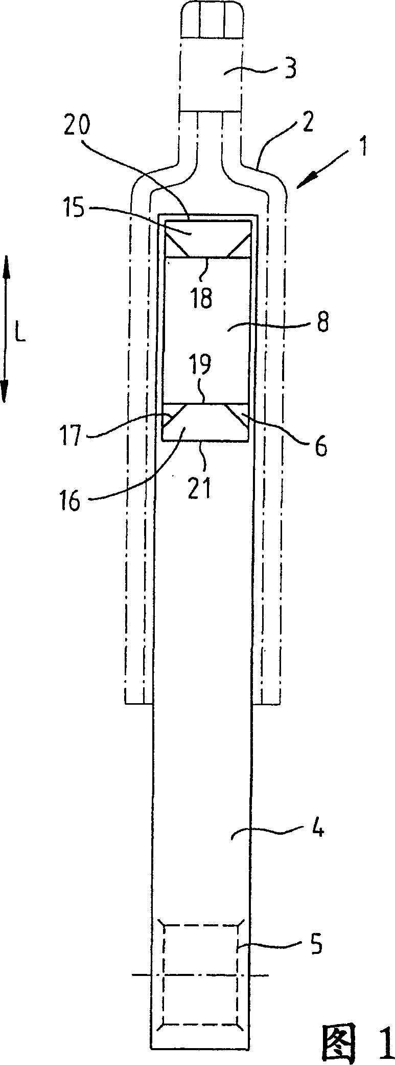
[0047] The friction damper 1 according to FIG. 1 comprises a housing 2 on which a fastening ring bore 3 is provided.

[0048] A push rod 4 is guided in the housing 2 , which also has a fastening ring hole 5 at the end opposite the fastening ring hole 3 . The fixing ring holes 3, 5 are used for fastening or fixing on the bottom frame of the drum type washing machine on the one hand, for example, and on the washing drum on the other hand.

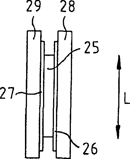
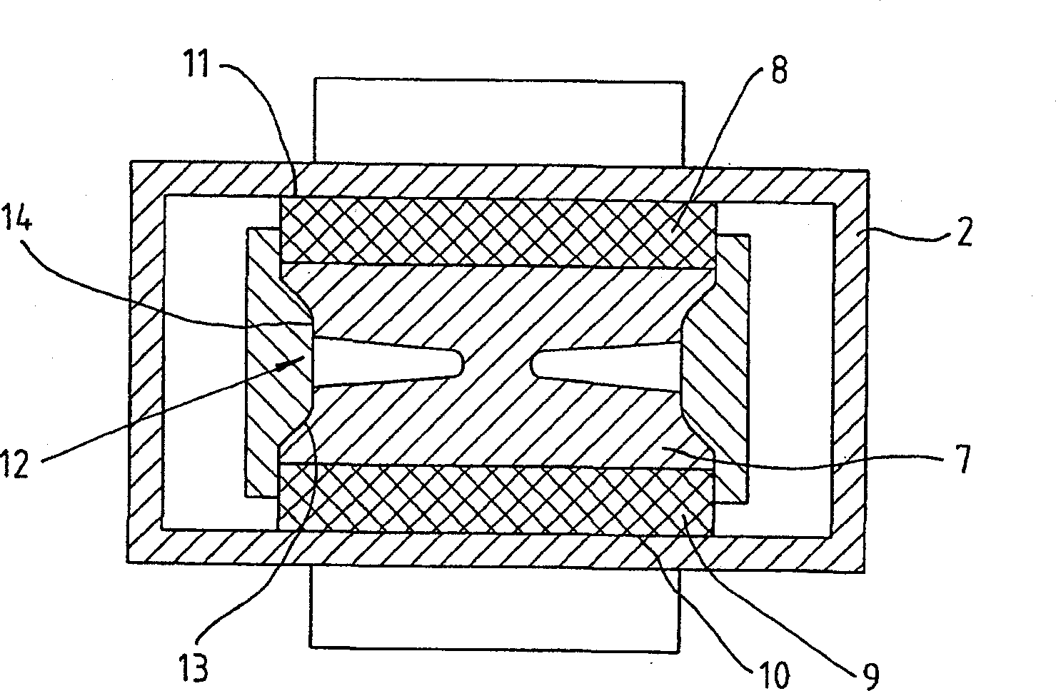
[0049] The plunger 4 is provided at its end in the housing 2 with a rectangular window or through-opening 6 . In said through hole 6, a sliding block or receiving part 7 is displaceably supported in the longitudinal direction, ie in the direction of the double arrow L (see figure 2 ). The receptacle 7 carries two friction coatings 8 , 9 on both sides, which engage with the respective friction surfaces 10 , 11 at a set tension via friction adhesion / friction connections.

[0050] Such as figure 2 As shown, a groove 13 machined into the rece...


PUM


Abstract

The invention relates to a frictional damper, especially for cylinder washing machines comprising a spin gear, said frictional damper having a housing (2) and a displaceable tappet (4) which is arranged in the housing (2) parallel to the longitudinal axis of the housing and extends out of the housing (2), and is provided with at least one window (6) on the end thereof in the housing (2). Said window (6) comprises at least one receiving part (7) that can be longitudinally displaced in relation to the tappet (4) and is used to receive a friction lining (8, 9), and at least one amplitude-dependent impact element (15, 16) for braking the movement of the receiving part (7). The inventive frictional damper is characterised in that the impact element (15, 16) is arranged between an inner surface (20, 21) of the window (6) and an outer surface (18, 19) of the receiving part (7).

Description

technical field [0001] The invention relates to a friction damper, in particular for a drum washing machine, according to the preamble of claim 1 . Background technique [0002] Known from European publication EP 407755 is a friction damper which has a piston rod guided coaxially in a cylindrical housing and at the end of the piston rod located in the housing There is a sleeve with a friction coating, which resists the axial displacement of the spring element or damping element relative to the piston rod. The spring is supported between separate stops. Therefore, the spacer sleeve is moved by the piston rod only after a certain (movement) amplitude or stroke of the piston rod in the housing. The spring force or damping effect thus achieved is linear or proportional in the range of the spring and constant in the range of the friction coating on the two stages of the amplitude. This arrangement is cylindrical, so that the spacer sleeve, the friction coating and the damping ...

Claims


Application Information

Patent Timeline
Patent Type & Authority Applications(China)
IPC IPC(8): D06F37/20F16F7/08F16F7/09
CPCF16F7/09D06F37/20
Inventor G·迪尔曼K·瓦勒斯托佛尔
Owner SUSPA
Why Eureka
Try Eureka