
Method and device for limiting the current in a liquid metal current limiter

A liquid metal, current limiting device technology, applied in circuit breakers with excessive current, emergency protection devices, high voltage/high current switches, etc., can solve the problems of arc oxidation and expensive

Inactive Publication Date: 2006-08-16
ABB RES LTD
View PDF4 Cites 9 Cited by
  • Summary
  • Abstract
  • Description
  • Claims
  • Application Information

AI Technical Summary

Problems solved by technology

The disadvantage of this is that hierarchical current limiting is not possible and arcing between the solid electrodes causes oxidation in the liquid metal
The structure of this high current switch includes a seal for liquid metal, noble gas or vacuum and is quite expensive

Method used


Image

  • Method and device for limiting the current in a liquid metal current limiter
  • Method and device for limiting the current in a liquid metal current limiter
  • Method and device for limiting the current in a liquid metal current limiter

Examples


Embodiment Construction

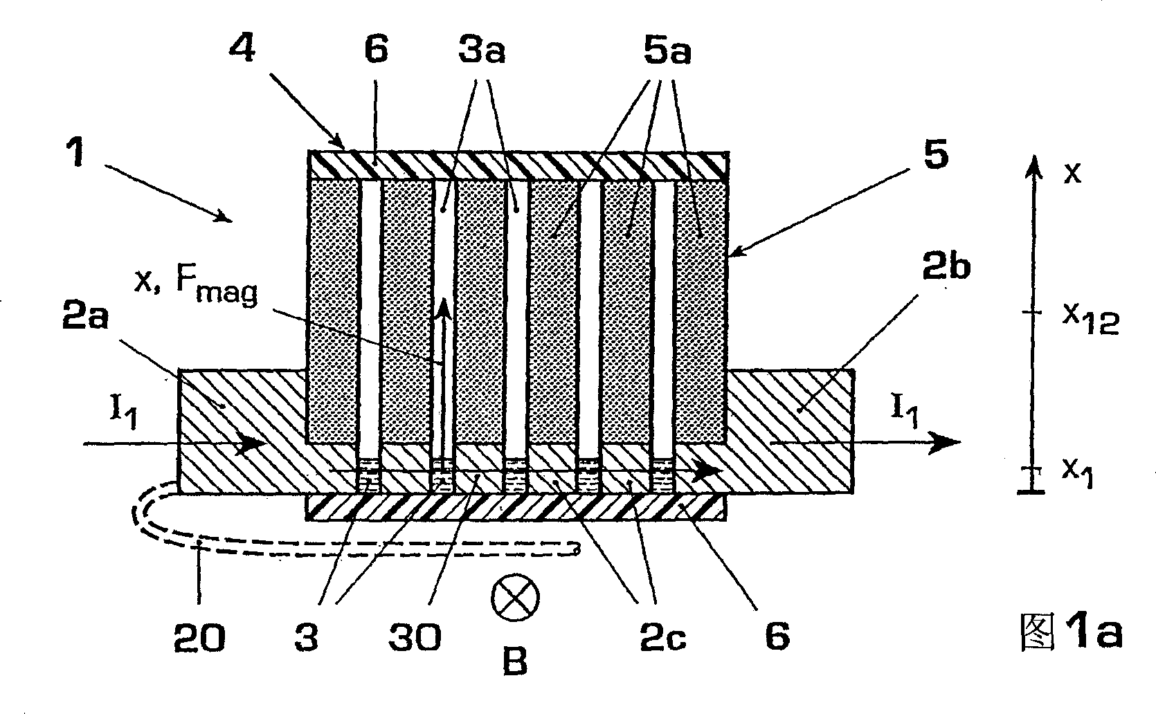
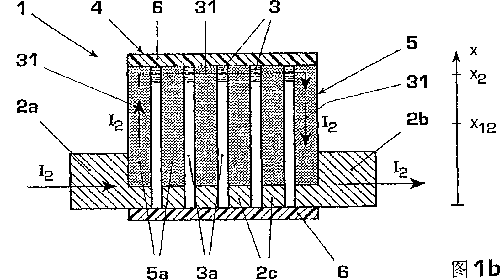
[0023] Figures 1a, 1b show an embodiment of a flow restrictor 1 of the liquid metal type. The current limiter 1 comprises solid metal electrodes 2a, 2b and an intermediate electrode 2c for a current lead 20 and a container 4 for liquid metal 3 . The container 4 has a bottom 6 of insulating material and a cover 6, between which an electrical impedance device 5 with at least one channel 3a for the liquid metal 3 is arranged. Above the liquid metal body 3 , for example, a protective gas, an insulating liquid (with escape volume not shown in the figure) or a vacuum can be provided.

[0024] In the first working state (see Figure 1a), the working current or rated current I 1 , on a rated current path 30 from the input electrode 2a via the liquid metal 3 and optionally via the intermediate electrode 2c to the output electrode 2b. In this case, the liquid metal 3 is in the first position X 1 , the solid electrodes 2a, 2b, 2c are at least partially wetted and bridge the channel 3a ...


PUM


Abstract

The invention relates to a current limiting method, a current limiting device (1), and a switchgear comprising such a device (1). According to the invention, liquid metal (3) is directed along a resistor element (5) for the current limiting path (31) so as to obtain arc-free current limitation for mains-related fault currents (i(t)). Examples of embodiments include, among other things: an electrical resistance (Rx) that increases in a non-linear manner in the direction of movement (x) of the liquid metal (3) for a smooth current limiting characteristic; a resistor element (5) in the form of a dielectric matrix (5) comprising channels (3a) for the liquid metal (3), and a combined current limiter-circuit breaker (1). Advantages include, among other things: arc-free, reversible current limitation and optional power shutdown; suitable also for high voltages and currents; fast reaction times; reduced wear; and maintenance-friendly.

Description

technical field [0001] The invention relates to the main field of technology for use in electrical switchgear, in particular for limiting fault currents in high-voltage, medium-voltage or low-voltage switchgear, the invention emerges from the preamble of an independent claim for current limiting The method and device and the switchgear with the device. Background technique [0002] DE19903939A1 discloses a current limiting device with white recovery of liquid metal. A pressure-resistant insulating box is provided between the two solid metal electrodes, in which liquid metal is arranged in the compressor chambers and the connecting channels connecting these compressor chambers located therebetween, so that there is a gap between the solid electrodes. provides a current path for the rated current. The current path in these connecting channels is narrower than the current path in the compressor chamber. In the event of a short-circuit current, these connecting channels are h...

Claims


Application Information

Patent Timeline
Patent Type & Authority Applications(China)
IPC IPC(8): H01H77/10H01H29/00H01H29/22H01H53/08
CPCH01H77/10H01H53/08H01H29/22H01H29/00H01H33/04H01H29/28
Inventor 卡韦赫·尼亚耶什弗里德里希·柯尼希
Owner ABB RES LTD
Learn More