Method for using a refrigeration system to remove waste heat from an ultrasound transducer

An ultrasonic transducer and transducer technology, applied in the direction of household refrigeration equipment, machine operation mode, refrigerator, etc., can solve the problems of practical methods for transferring fluid into/out of the system, etc.

Inactive Publication Date: 2006-08-23
SIEMENS MEDICAL SOLUTIONS USA INC
View PDF2 Cites 18 Cited by
  • Summary
  • Abstract
  • Description
  • Claims
  • Application Information

AI Technical Summary

Problems solved by technology

Practical methods for transferring fluid in and out of the system can be difficult if the transducer assembly is detachable from the system connector

Method used


Image

  • Method for using a refrigeration system to remove waste heat from an ultrasound transducer
  • Method for using a refrigeration system to remove waste heat from an ultrasound transducer
  • Method for using a refrigeration system to remove waste heat from an ultrasound transducer

Examples


Embodiment Construction

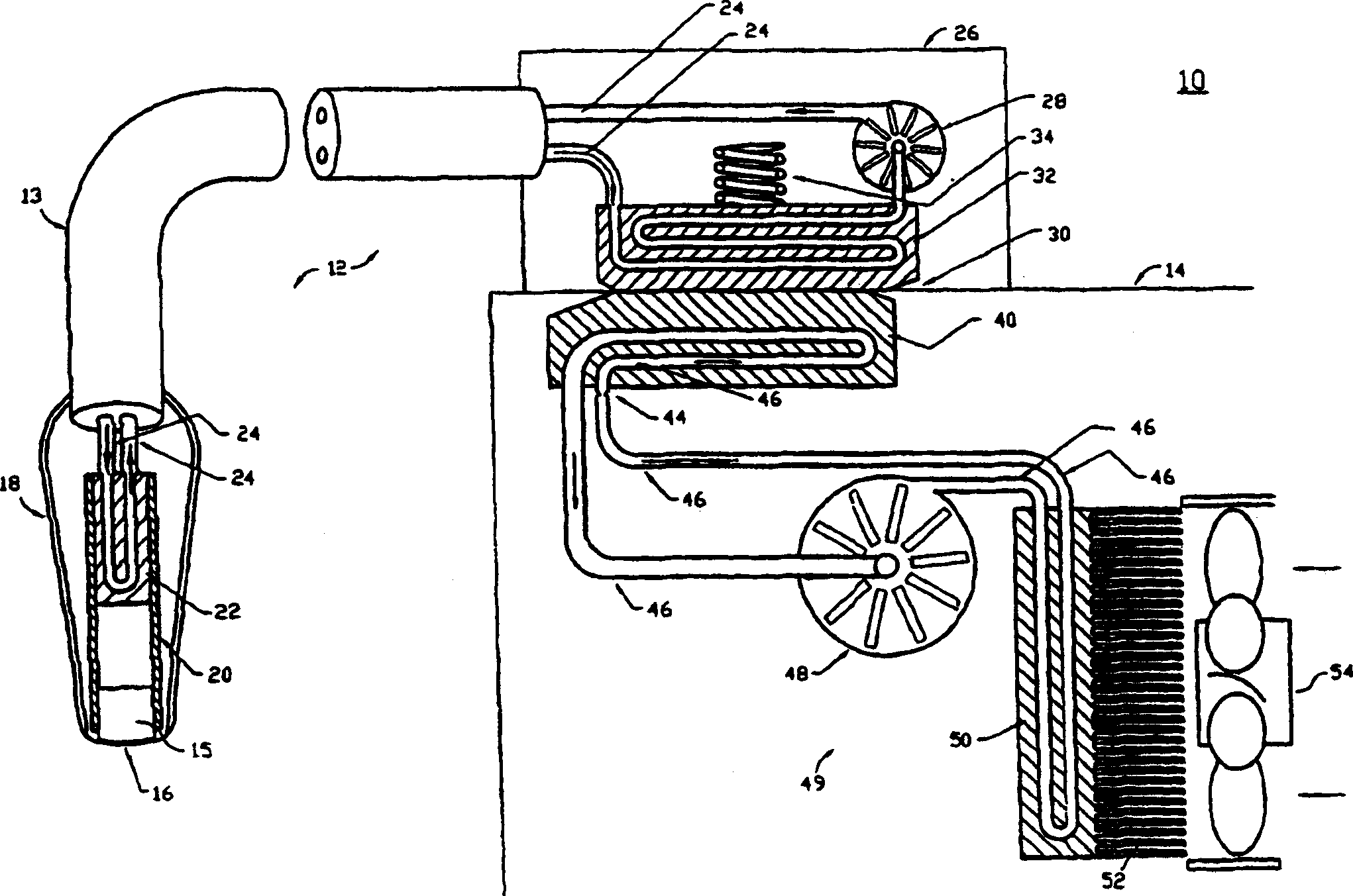
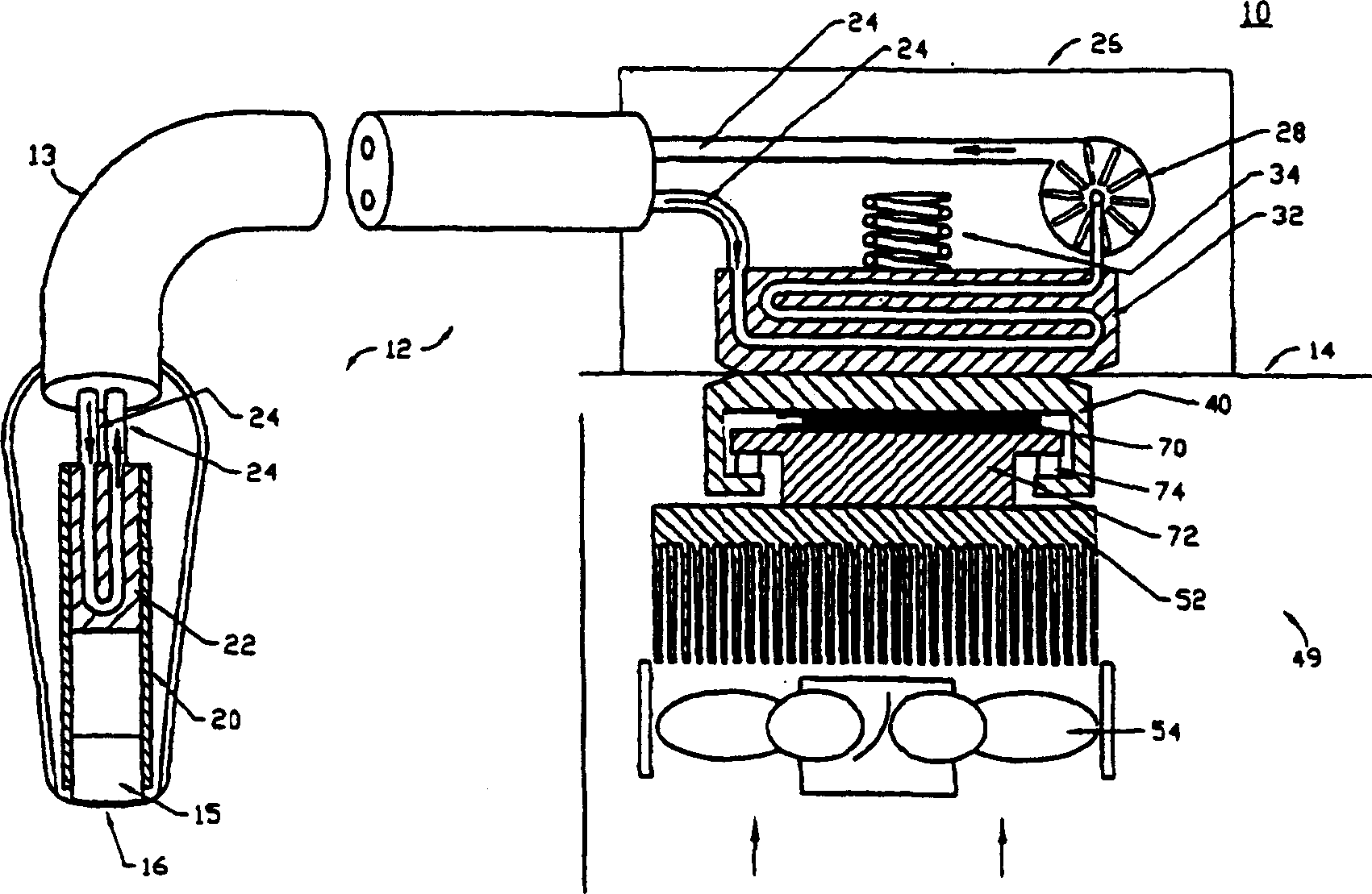
[0020] Regulations require that ultrasound transducers used in medical diagnostic procedures be limited to a temperature not exceeding 43°C, where the transducer is in contact with a patient. For an assumed ambient air temperature of 25°C, a temperature difference of only 18°C ​​facilitates heat removal through passive methods including natural convection, conduction, and radiation.

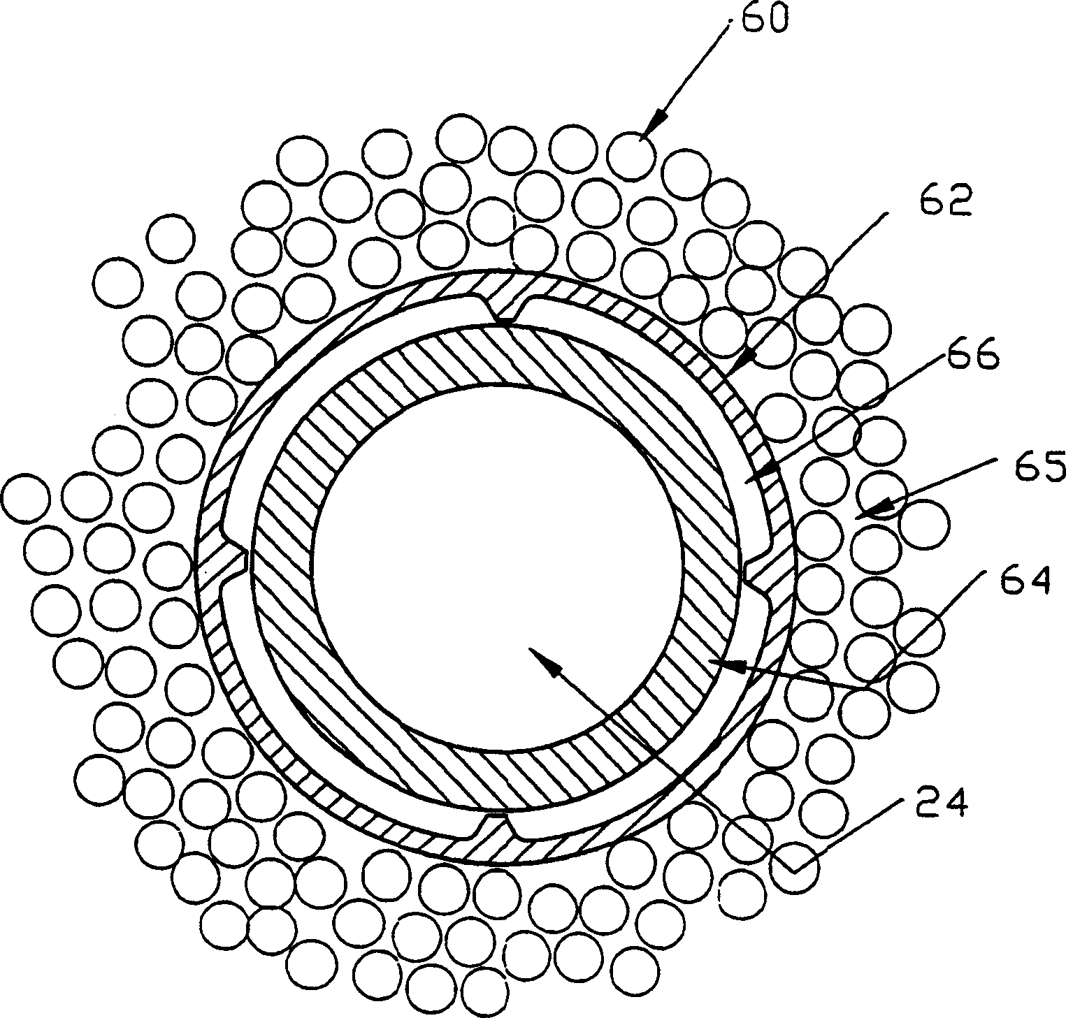
[0021] To provide additional heat removal, a cooling system within the transducer assembly utilizing recirculated liquid coolant is used, which transfers waste heat from heat-generating acoustic components or electronics within the transducer along its cables to the transducer connector. Instead of trying to dissipate waste heat in relatively small connectors, heat is transferred into the ultrasound imaging system by thermal conduction. Once in the imaging system, the waste heat is dissipated to the atmosphere with the help of a vapor / liquid or some other type of refrigeration system. Because r...


PUM


Abstract

Methods and systems are provided for cooling an ultrasound transducer using a refrigeration system located within the imaging system. A closed loop of recirculating coolant located in the transducer assembly transports waste heat from the remotely located heat producing acoustic components or active electronics components to a thermally conductive shoe, located within the transducer connector. Thermally conductive materials in each connector, the ultrasound system connector and the transducer assembly connector, are positioned in contact to thermally conduct heat from the transducer assembly to a refrigeration system, located in the imaging system, free of fluid transfer.

Description

technical field [0001] The invention relates to the cooling of ultrasonic transducers for diagnostic use. Ultrasonic piezoelectric devices and associated electronics for medical diagnostics generate significant waste heat during operation. In general, transducers that operate at higher power levels are advantageous. Such transducers provide superior diagnostic performance due to the increased energy delivery into the body. Integrating a heat-generating low-noise amplifier close to the acoustic receiver improves the signal-to-noise performance of the measured ultrasonic energy. Background technique [0002] There are regulatory limitations on the temperature allowed on the transducer surface. For example, the regulatory limit for surfaces of diagnostic ultrasound transducers intended to come into contact with a patient is 43°C. [0003] Typically, the waste heat generated in the transducer is dissipated to the patient or the surrounding environment by passive means. Due ...

Claims


Application Information

Patent Timeline
Patent Type & Authority Applications(China)
IPC IPC(8): A61B8/00G10K11/00
CPCF25B21/02F28F13/00F28D15/0266H04R9/022A61B8/546F28F2250/08F25B25/005F25B1/00F28D2021/0029F28D15/00A61B8/00F25D19/006F25B2321/0251F28D15/0275B65G47/52B65G47/04B65G2201/0267B65G2203/0233B65G2203/042
Inventor V·R·马里安W·J·帕克T·E·彼得森
Owner SIEMENS MEDICAL SOLUTIONS USA INC
Why Eureka
Try Eureka