
Method and device for real-time correcting infrared measuring temperature

A technology of infrared temperature measurement and infrared camera, applied in measuring devices, radiation pyrometry, optical radiation measurement, etc., can solve the problems of inaccurate temperature measurement and poor comparability of heat maps, etc. Poor graph comparability and the effect of eliminating the interference of the collected signal

Inactive Publication Date: 2006-08-23
AVIATION MEDICINE INST AIR FORCE PLA +1
View PDF0 Cites 53 Cited by
  • Summary
  • Abstract
  • Description
  • Claims
  • Application Information

AI Technical Summary

Problems solved by technology

[0005] The technical problem to be solved by the present invention is to provide a method and device for real-time calibration of infrared temperature measurement. Using this method and device can effectively eliminate the interference of external factors on the signal collected by the infrared temperature sensor, and solve the problem of inaccurate temperature measurement during infrared detection. The problem of poor comparability with the heat map, and the absolute temperature of the measured object can be measured

Method used


Image

  • Method and device for real-time correcting infrared measuring temperature
  • Method and device for real-time correcting infrared measuring temperature
  • Method and device for real-time correcting infrared measuring temperature

Examples


Embodiment 1

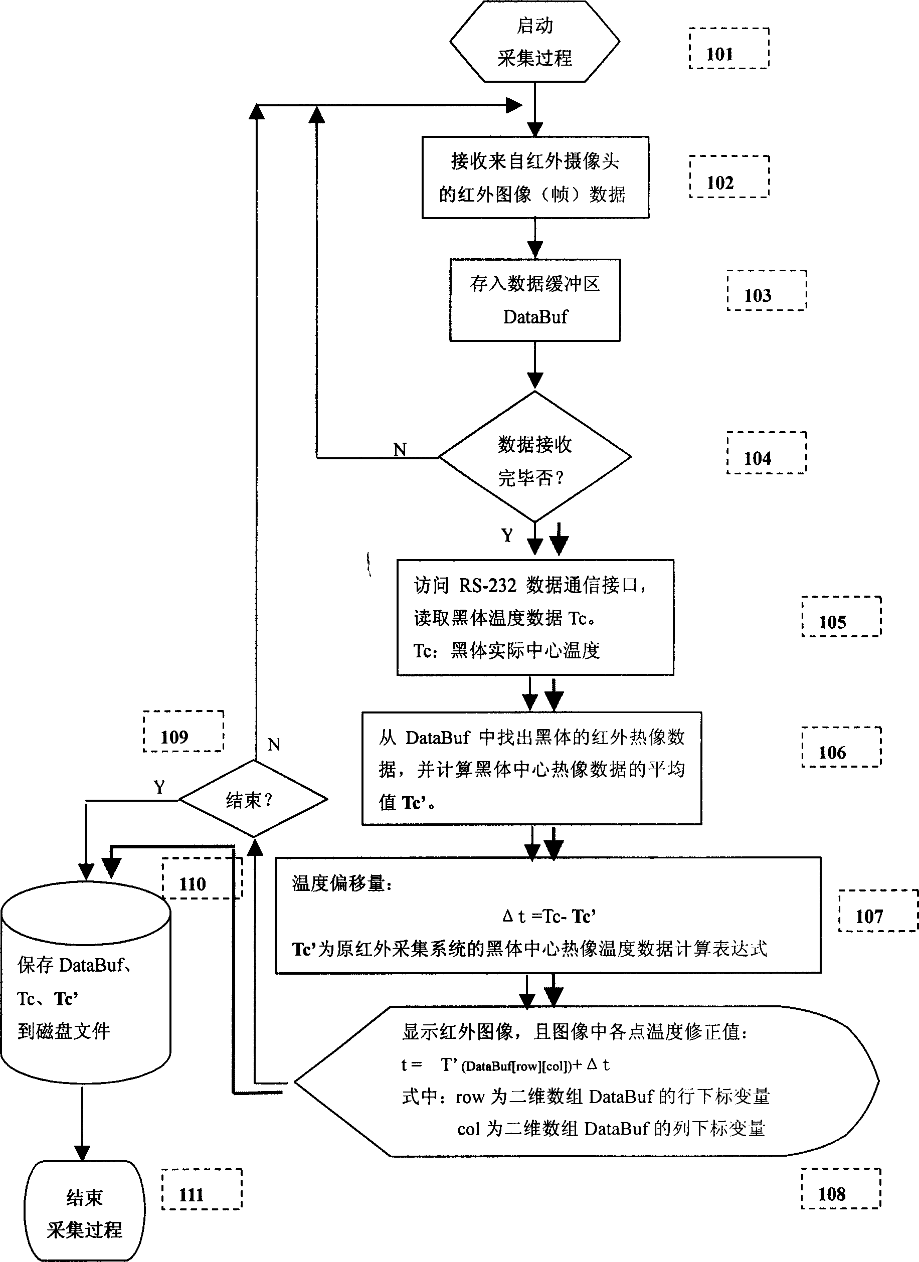
[0023] This example is a real-time calibration method and device for infrared temperature measurement for human body temperature measurement.

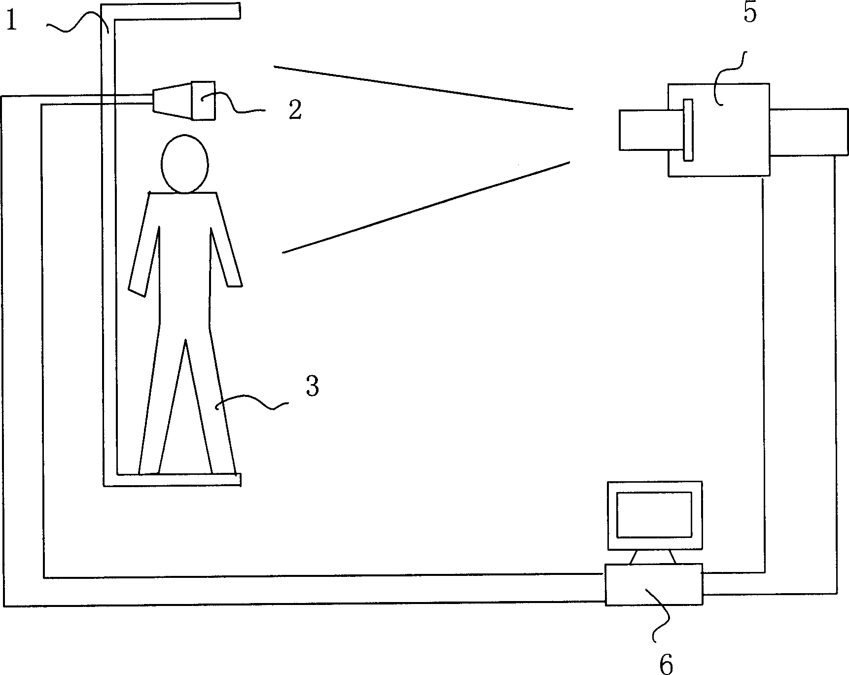
[0024] see figure 1 , the device used in this example method is provided with an infrared camera 5, the infrared camera is electrically connected to the computer 6 through a data line, and is provided with a frame 1 capable of positioning the measured object 3, and is provided with the same data acquisition device as the measured object in the frame. Surface, and constant temperature source 2 that can keep the temperature constant during the test. The infrared emissivity of the constant temperature source is 0.98, which is the same as that of the human body. The central temperature output end of the constant temperature source is connected to the reference signal input end of the computer.

[0025] The above-mentioned infrared camera adopts the model ATIR-M301 sold by Chongqing Weilian Company.

[0026] The constant temperature source...

Embodiment 2

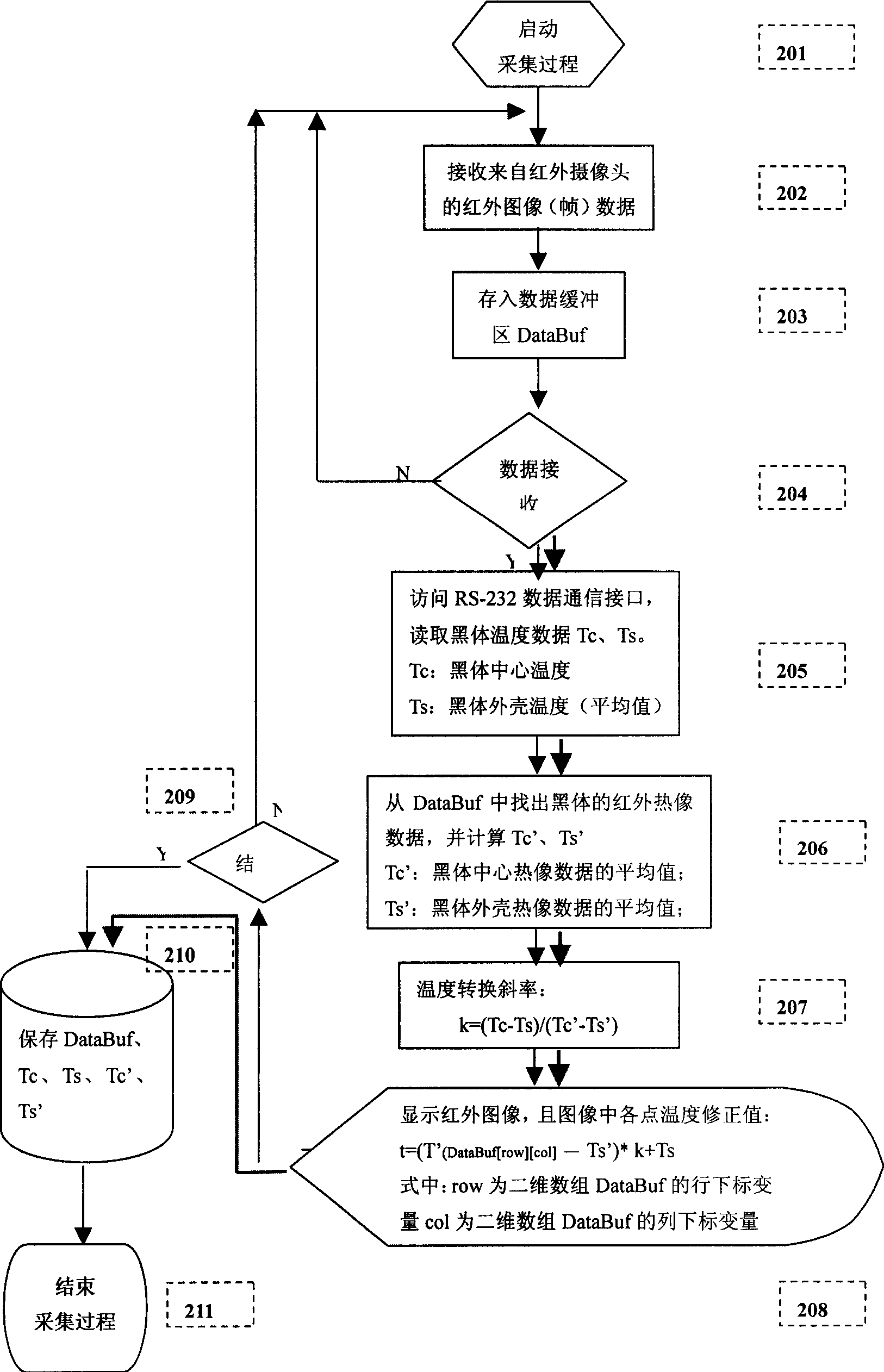
[0049] The difference from Example 1 is that the blackbody source in this example has two temperature output terminals, the central temperature and the outer shell temperature, which are connected to the computer, and a multi-point blackbody-infrared image data acquisition method is adopted correspondingly, that is, the central temperature value of the blackbody source is collected The two temperature values ​​of Tc and shell temperature Ts are used as sampling standards, and the thermal image temperature data value Tc' of the blackbody source center and the shell thermal image temperature data value Ts' are obtained through the computer, and then the temperature offset rate obtained by the above data is used

[0050]k=(Ts-Tc) / (Ts’-Tc’) to calibrate the temperature data value of each point of the thermal image of the measured object.

[0051] Referring to Fig. 4, the collection and processing steps of the above-mentioned data by the computer include:

[0052] 201: Start the co...


PUM


Abstract

This invention relates to a real-time calibration method and a device for infrared temperature test, which sets an infrared camera head used in collecting the infrared radiation signals of a tested object, sets a constant temperature source same to the infrared radiation rate of the tested object, in which, the source is on the same data collection surface with the tested object, the infrared radiation signals of the object and the constant temperature source are input into the computer to be processed to form a heat picture, at the same time, the real temperature value of the source is collected to get the temperature deviation value to calibrate the heat picture temperature data value of the tested object.

Description

technical field [0001] The invention belongs to a system and method for infrared temperature measurement. Background technique [0002] Any substance above absolute zero (-273°C) in nature has a certain amount of infrared energy and forms an energy field around it. The infrared energy of different substances may have different infrared wavelength ranges (for example, the main infrared wavelength of the human body is 8-14 μm) and energy intensity. Infrared energy travels in the form of light waves. People can feel this infrared energy——temperature, but human eyes cannot directly observe infrared waves. An infrared camera composed of infrared photosensitive devices can detect infrared thermal radiation of objects. When the infrared energy value of the measured object is higher than the surrounding environment, the infrared thermal imaging camera can collect the invisible infrared radiant energy of the object through the infrared camera system and convert it into a digital s...

Claims


Application Information

Patent Timeline
IPC IPC(8): G01J5/02G01J5/00
Inventor 俞梦孙沈显威杨军蔡佩斯王乃中邓秀芳
Owner AVIATION MEDICINE INST AIR FORCE PLA
Learn More