Calorimeter of external bucket with closed chamber circulation temperature contoller
A temperature control device and closed-circuit cavity technology, applied in the field of calorimeters, can solve the problems of large differences in the heat capacity of the instruments, reduced accuracy of test results, and uncertainty of intensity, etc. Circulation system temperature influence, the effect of enhancing stability
- Summary
- Abstract
- Description
- Claims
- Application Information
AI Technical Summary
Problems solved by technology
Method used
Image
Examples
Embodiment 1
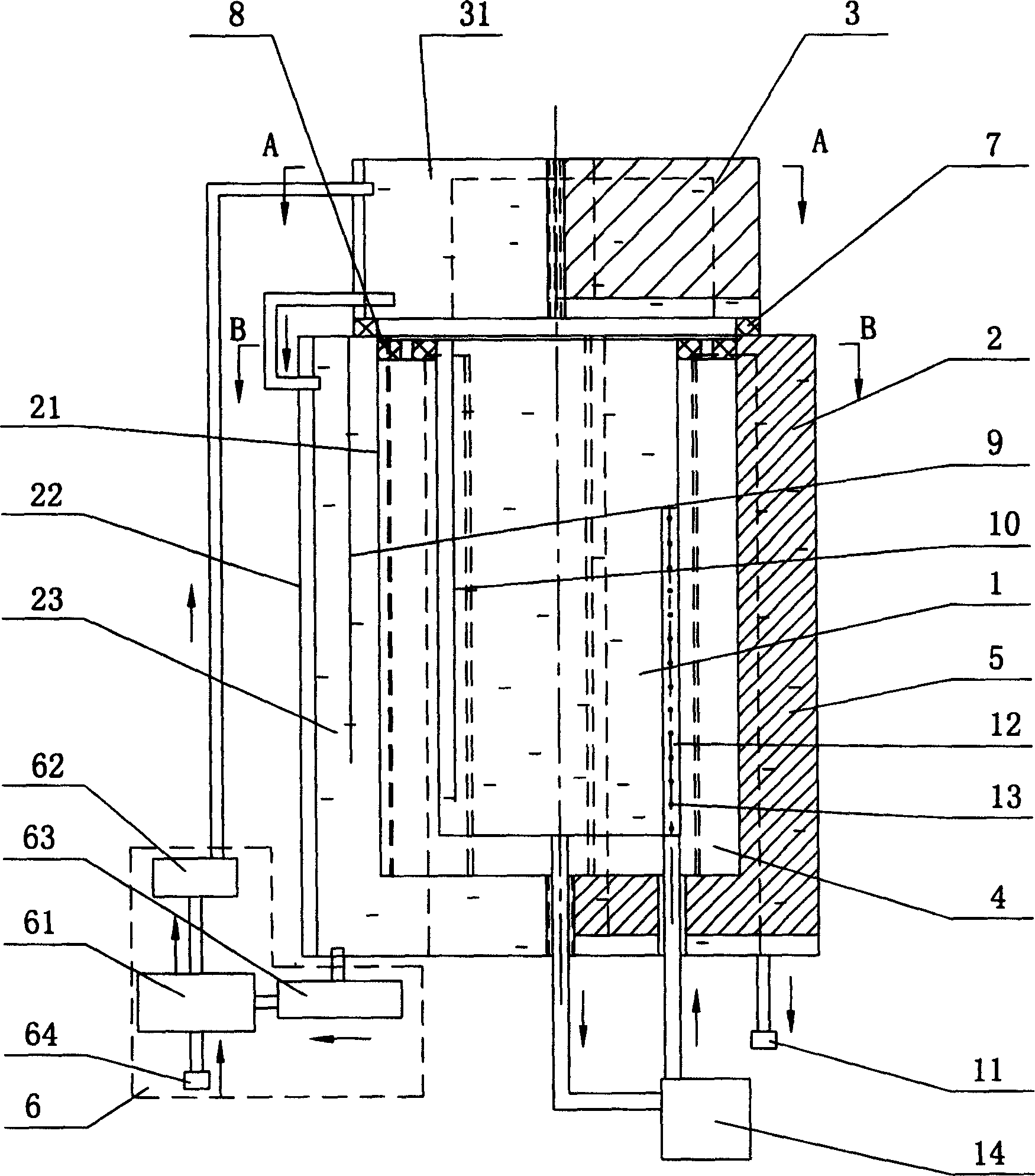
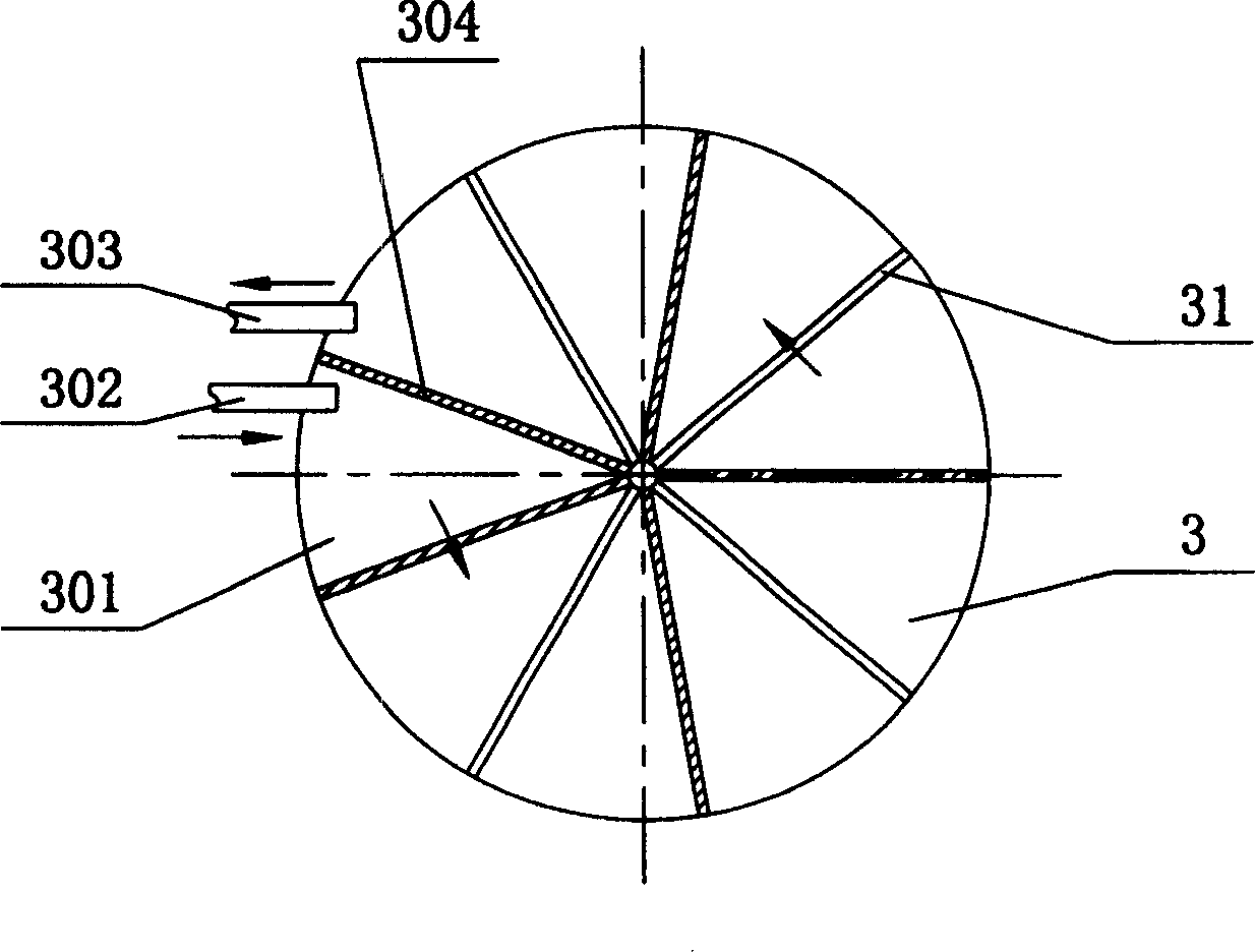
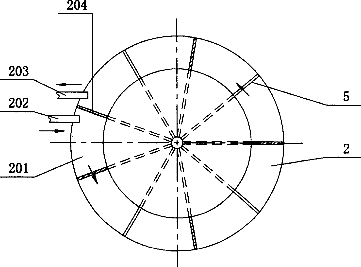
[0054] Embodiment 1: as figure 1 and image 3 As shown, the outer barrel partition 5 is radially arranged in the outer barrel cavity 23 along the center line of the outer barrel 2, along the flow direction of the medium, between the first sub-cavity 201 and the last sub-cavity 201 A third intermediate partition 204 is provided, which completely separates the medium inlet part and the medium outlet part. Wherein, part of the outer tub partition 5 is connected with the top of the outer tub cavity 23, and another part of the outer tub partition 5 is connected with the bottom of the outer tub cavity 23, so the outer tub partition 5 is connected with the outer tub cavity 23 There is a gap between the inner wall of the top end or the inner wall of the bottom end to allow the medium to pass through, so that the various sub-cavities 201 are connected to each other in turn, and the medium can flow from the first sub-cavity 201 through each sub-cavity 201 to the last sub-cavity. Cavit...
Embodiment 2
[0055] Embodiment 2: as Figure 4 and Figure 6 As shown, in this embodiment, the outer barrel partition 5 is radially arranged in the outer barrel cavity 23 along the centerline of the outer barrel 2, and along the flow direction of the medium, the first secondary cavity 201 and the last secondary cavity 201 A third intermediate partition 204 is provided therebetween, and the third intermediate partition 204 completely separates the medium inlet part and the medium outlet part. Wherein, there is a gap that allows the medium to pass between part of the outer tub partition 5 and the outer wall of the outer tub cavity 23, and a gap that allows the medium to pass is maintained between part of the outer tub partition 5 and the adjacent outer tub partition 5. , so that each sub-cavity 201 communicates with each other in turn, the medium can flow from the first sub-cavity 201 through each sub-cavity 201 to the last sub-cavity 201, during the flow process, due to each sub-cavity 201...
Embodiment 3
[0056] Embodiment 3: as Figure 7 and Figure 9 As shown, in this embodiment, the outer tub partitions 5 are arranged in parallel in the outer tub cavity 23, wherein some of the outer tub partitions 5 are connected to the top of the outer tub cavity 23, and some of the outer tub partitions 5 are connected to the outer tub cavity 23. The bottom of the barrel cavity 23 is connected, so there is a gap between the outer barrel partition 5 and the top inner wall or the bottom inner wall of the outer barrel cavity 23 to allow the medium to pass through, so that the secondary cavities 201 are connected to each other in sequence, The medium can flow from the first sub-cavity 201 through each sub-cavity 201 to the last sub-cavity 201. During the flow process, since the communication positions of each sub-cavity 201 are inconsistent, the medium passes through each sub-cavity The speed and direction of movement of the body 201 are different, and the volume passed through will also be di...
PUM
 Abstract
Description
Claims
Application Information
 - R&D Engineer
- R&D Manager
- IP Professional
- Industry Leading Data Capabilities
- Powerful AI technology
- Patent DNA Extraction
Browse by: Latest US Patents, China's latest patents, Technical Efficacy Thesaurus, Application Domain, Technology Topic, Popular Technical Reports.
© 2024 PatSnap. All rights reserved.Legal|Privacy policy|Modern Slavery Act Transparency Statement|Sitemap|About US| Contact US: help@patsnap.com


