
Device and method for polishing large parts

A large-scale parts and equipment technology, applied in the field of large-scale parts polishing equipment, can solve problems such as time-consuming and labor-intensive surface conditions, difficult to polish surfaces, uneven polished surfaces, etc., and achieve the effect of improving quality

Inactive Publication Date: 2006-08-23
KK TOSHIBA
View PDF1 Cites 10 Cited by
  • Summary
  • Abstract
  • Description
  • Claims
  • Application Information

AI Technical Summary

Problems solved by technology

However, because the size of turbine parts is very large and the shape is extremely complicated due to the steam inflow characteristics, and such narrow parts must be polished, it is difficult to polish automatically or mechanically, and usually by using compressed air and electric rotary tools Time-consuming improvement of the surface condition of turbine components
[0013] In order to ensure the final surface roughness required to improve the performance of turbine parts, it is necessary to polish in large shapes such as nozzle rings, so the polishing work is very heavy, the environment is poor and it takes a long time
[0014] On the other hand, in manual polishing tools, small flaws are formed when polishing narrow parts, especially it is difficult to obtain a uniform polished surface, and it cannot be polished uniformly along the steam inflow direction and the orthogonal direction, so that the polished surface is tends to be uneven
[0015] In jet or honing machines, the surface state becomes too rough, and thus it is difficult to achieve the surface roughness to achieve the above-mentioned turbine performance, and it is not suitable as a finishing tool
[0016] In addition, in order to accurately obtain information from non-destructive inspection when performing on-site inspection or repair of existing steam turbines, it is necessary to use ceramic injection materials to clean the surface with air jets and remove oxide films, but from the viewpoint of improving surface roughness , there is room for further improvement

Method used


Image

  • Device and method for polishing large parts
  • Device and method for polishing large parts
  • Device and method for polishing large parts

Examples


Embodiment Construction

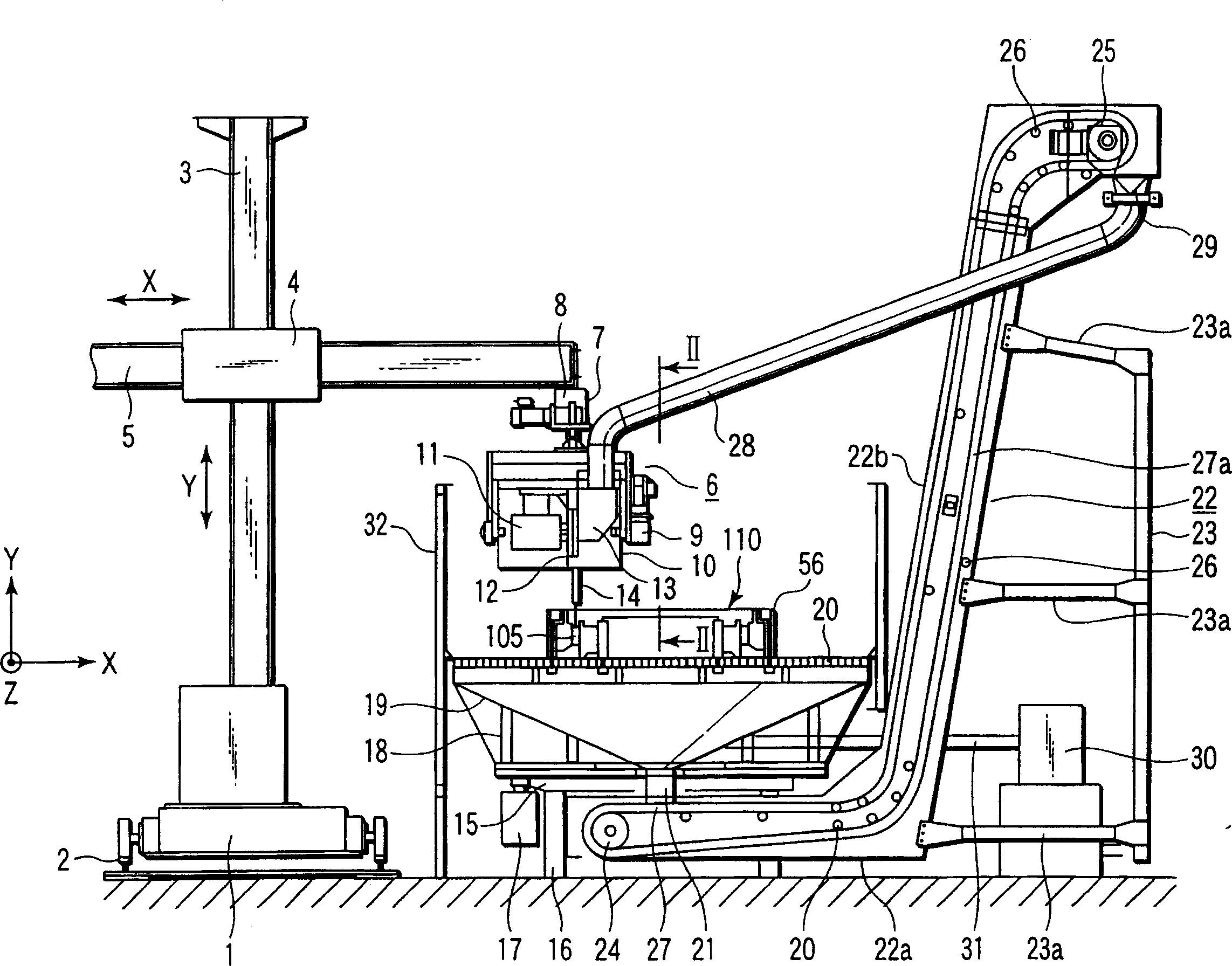
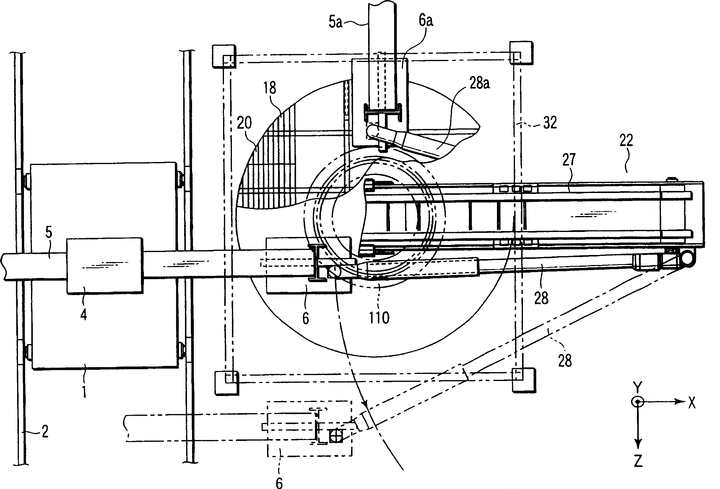
[0036] figure 1 is a front view showing a first embodiment of the large parts polishing apparatus according to the present invention, and figure 2 is a plan view of the first embodiment.

[0037] exist figure 1 and figure 2Among them, reference numeral 1 is a bracket capable of moving along the guide rail 2 in the Z-axis direction (vertical direction in the drawing), and a bracket 3 is vertically mounted on the bracket 1 . On the bracket 3, the manipulator support part 4 is movably installed along the Y-axis direction (vertical direction in the drawings), and the manipulator 5 is supported on the manipulator support part 4 so as to be able to move along the X-axis direction (vertical direction in the drawings). for the horizontal direction) movement. The carriage 1, the manipulator support 4 and the manipulator 5 are driven in respective directions by a driving source not shown in the drawings.

[0038] Reference numeral 6 is a polishing head attached to the front end...


PUM


Abstract

A device for polishing a large part, comprising a rotary table supporting a turbine part at a specified position, rotatably supported on a support member, and drivingly rotated by a drive motor, an abrasive material feed means feeding abrasive particles formed mainly of elastic bodies as an abrasive material to a specified position, a polishing head drivingly rotated by an impeller drive motor at a high speed, having an impeller providing rotating energy to the abrasive particles fed from the abrasive material feed means, and jetting the abrasive particles flying out in the tangential direction of the impeller at a predetermined speed toward the polished surface of the turbine part held on the rotary table, and an abrasive material recovery means recovering the abrasive particles fed from the polishing head thereto for the polishing of the turbine part and feeding the abrasive particles to the abrasive material feed means.

Description

technical field [0001] The present invention relates to a polishing apparatus and polishing method for large structural parts such as steam turbine parts by shooting and colliding abrasive grains having an elastic material to the surface thereof. Background technique [0002] In steam turbines, especially the moving blades, stationary blades, turbine rotors and steam passage parts (such as valves, steam pipes, cross pipes, turbine inlets, turbine outlets and nozzle box interiors), their surface roughness determines the performance of the turbine major factor, and the need to improve the surface roughness of the steam channel as much as possible (to make it smoother). [0003] Turbine parts are manufactured in multiple processes, and the manufacturing process of stator blades in particular includes multiple processes such as stator blade cutting process, assembly process, welding process, heat treatment process, polishing process, finishing process, finishing process and Che...

Claims


Application Information

Patent Timeline
Patent Type & Authority Applications(China)
IPC IPC(8): B24C5/06B24C9/00B24C1/08B24C3/24B24C11/00F01D5/00F01D25/00
CPCB24C11/00B24C9/003F01D5/005F05D2230/10F01D25/002B24C9/006F05B2230/90F05D2230/14B24C3/24F05D2230/90B24C1/08Y02P70/10
Inventor 谷中悟浅井知坪井竜介上村健司田沼唯士菊地正孝
Owner KK TOSHIBA
Learn More