Isolative linear displacement transmitter
A linear displacement and isolation technology, applied in the direction of measuring devices, using electric devices, and using electric/magnetic devices to transmit sensing components, etc., can solve the problems of wasting manpower and material resources, it is difficult to understand the amount of wear, and accidents are prone to occur. Achieve the effect of saving operating costs, extending safe operating time, and measuring range
- Summary
- Abstract
- Description
- Claims
- Application Information
AI Technical Summary
Problems solved by technology
Method used
Image

Examples
Embodiment Construction
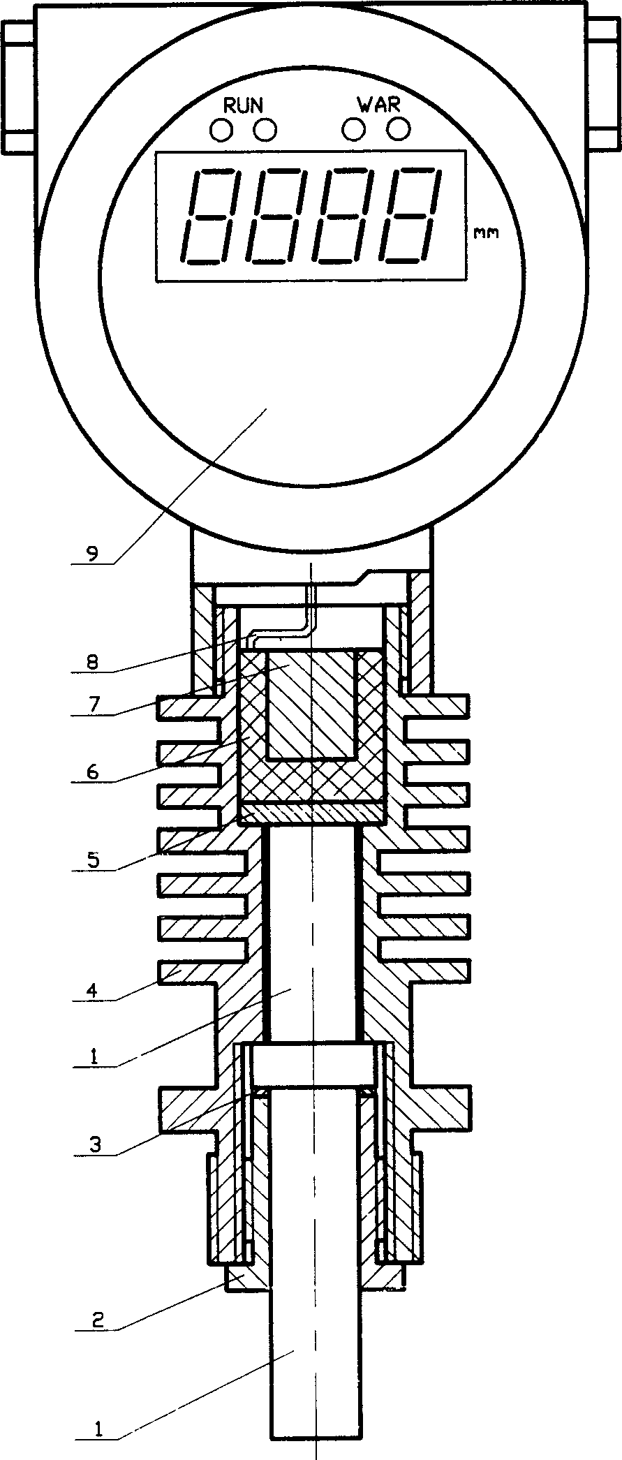
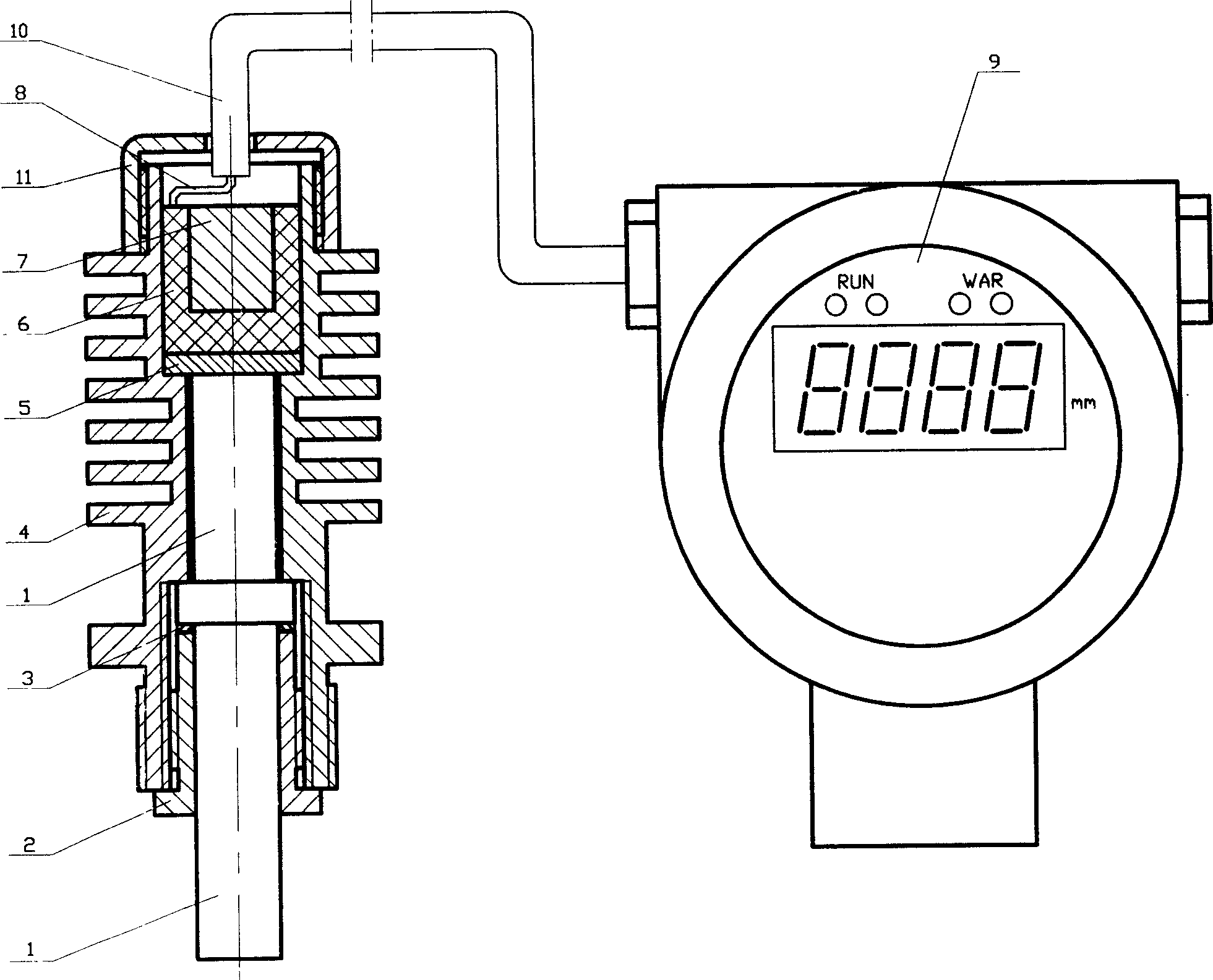
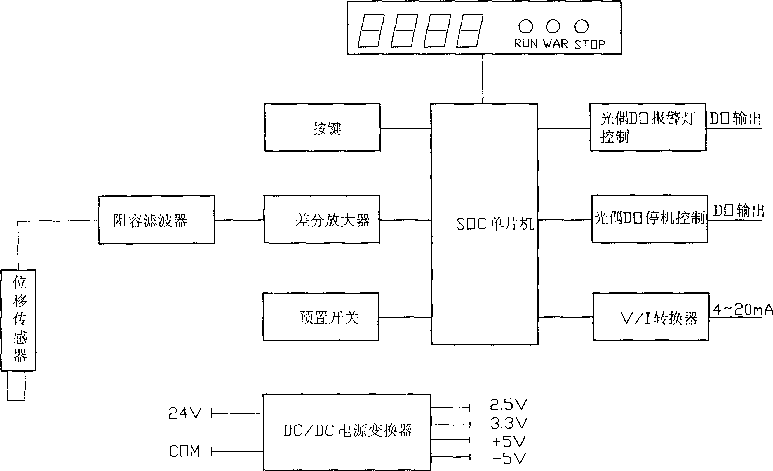
[0019] Such as figure 1 , an isolated linear displacement transmission device shown in 2, 3 and 4 is characterized in that it includes a displacement sensor head, a guide magnet, a Hall sensor and a radiator shell that can form a magnetic circuit with an external measurement ring The sensor and a transmitter consist of a transmitter housing, a microcontroller containing a microprocessor, an LED display and an intelligent control module. The Hall sensor and the transmitter described therein are electrically connected through a shielded cable, and the hose and / or thread are hard-connected through a stainless steel hose and / or thread between the sensor and the transmitter housing; while the Hall sensor housing The other end is threaded to the pump cover and / or bracket. The external measuring ring is installed on the transmission shaft of the application equipment. When the equipment is running, the measuring ring will produce axial serial motion along with the transmission shaft...
PUM
 Abstract
Description
Claims
Application Information
 - R&D
- Intellectual Property
- Life Sciences
- Materials
- Tech Scout
- Unparalleled Data Quality
- Higher Quality Content
- 60% Fewer Hallucinations
Browse by: Latest US Patents, China's latest patents, Technical Efficacy Thesaurus, Application Domain, Technology Topic, Popular Technical Reports.
© 2025 PatSnap. All rights reserved.Legal|Privacy policy|Modern Slavery Act Transparency Statement|Sitemap|About US| Contact US: help@patsnap.com