Electronic warp feeding system of warp knitting machine

An electronic warp let-off and warp knitting machine technology, applied in warp knitting, textiles, papermaking, knitting, etc., can solve the problem of difficulty in real-time control of warp let-off, not suitable for high speed, high precision, and inability to adapt to high product quality, etc. problem, to achieve the effect of convenient and intuitive operation interface, intuitive and clear alarm content, and good high-speed performance

Inactive Publication Date: 2006-09-06
康盘方
View PDF0 Cites 33 Cited by
  • Summary
  • Abstract
  • Description
  • Claims
  • Application Information

AI Technical Summary

Problems solved by technology

[0002] At present, the let-off control system of many domestic warp knitting machines is a mechanical let-off control system, which controls the let-off amount through a series of mechanical structures, but the efficiency of using the mechanical structure to control the let-off amount is extremely low, and its mechanical control The cloth and other products woven by the let-off system have great limitations in precision and flexibility. Most of the products are middle and low-end products, which are far from meeting the current industrial requirements for high-quality products.
In order to obtain better quality products, some units have also carried out research and development of electronic let-off control systems, such as using programmable logic controllers to control the let-off volume and tension, but the controller algorithms of these electronic let-off systems are simple. The speed is also relatively slow, and because it is an open-loop system, it is difficult to control the let-off amount in real time, and it cannot achieve a good control effect
There are already some machines including electronic warp let-off system in foreign countries, such as the independent electronic warp let-off system developed by Germany's Begra Company, which uses a stepping motor, and its speed control adopts open-loop control, but it is not suitable for high-speed, high-precision requirements

Method used


Image

  • Electronic warp feeding system of warp knitting machine
  • Electronic warp feeding system of warp knitting machine
  • Electronic warp feeding system of warp knitting machine

Examples


Embodiment Construction

[0024] Below in conjunction with embodiment and accompanying drawing, the present invention will be further described:

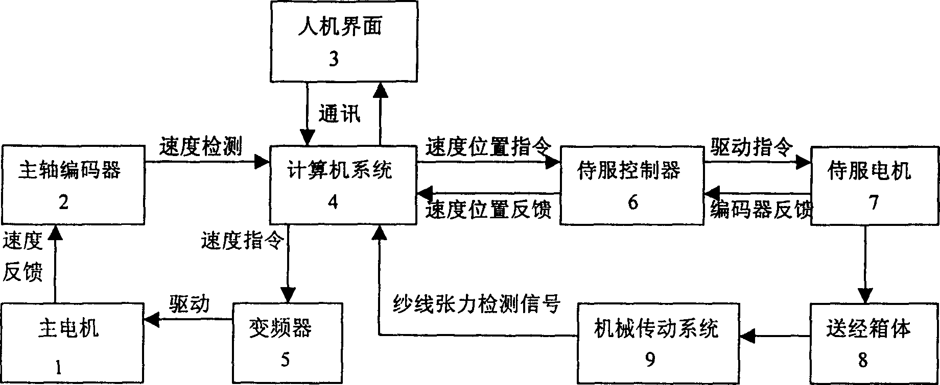
[0025] As shown in Figure 1, the present invention consists of a main motor 1, a spindle encoder 2, a computer system 4, a frequency converter 5, a servo controller 6, a servo motor 7, a let-off box 8 and a mechanical transmission system 9. The output shaft of the motor 1 is connected with the rotating shaft of the main shaft encoder 2 through a belt, which drives the main shaft encoder 2 to rotate and output the encoding signal, and the main shaft encoder 2 outputs the rotational speed encoding signal of the main motor 1 to the computer system 4 (using a common PC After that, through the calculation and processing of the specially compiled control software, the various process parameters of weaving input to the man-machine interface 3 (touch operation screen), such as the let-off amount, rotating speed, circumference, density, etc., and the computer system 4...


PUM


Abstract

The invention relates the warp knitting machine electronic let-off system, comprising main motor(1), chief axis encoder(2), computer system(4), converter(5), controller(6), motor(7), warp let-off box(8) and mechanical gearing system(9). The computer system (4) controls the main motor by converter (5). On the base of real-time rotary speed detection signal, the computer enters processing parameter and sends active instruction. The invention has the advantages of high-speed property, exact and steady warp run-in, easy adjustment, short operation processing time, and adopting multiple speed and position reaction to realize optimum dynamic adjustment.

Description

technical field [0001] The invention relates to an electronic system, in particular to an electronic let-off system of a warp knitting machine. Background technique [0002] At present, the let-off control system of many domestic warp knitting machines is a mechanical let-off control system, which controls the let-off amount through a series of mechanical structures, but the efficiency of using the mechanical structure to control the let-off amount is extremely low, and its mechanical control The cloth and other products woven by the let-off system have great limitations in terms of precision and flexibility. Most of the products are medium and low-end products, which are far from meeting the requirements of the current industrial pursuit of high-quality products. In order to obtain better quality products, some units have also carried out research and development of electronic let-off control systems, such as using programmable logic controllers to control the let-off volum...

Claims


Application Information

Patent Timeline
Patent Type & Authority Applications(China)
IPC IPC(8): D04B27/00
Inventor 王建荣彭永生
Owner 康盘方
Why Eureka
Try Eureka