
Constant speed variable pitch straight wing all direction propeller

A thruster and speed-changing technology, which is applied in the direction of rotary propellers, mechanical gear transmissions, etc., can solve the problems of multiple equipment, loose equipment arrangement, and low propulsion efficiency, and achieve high thrust, high efficiency, and excellent high-speed performance. Effect

Active Publication Date: 2014-11-19
ZHEJIANG FENGSHEN MARINE ENG TECH
View PDF7 Cites 7 Cited by
  • Summary
  • Abstract
  • Description
  • Claims
  • Application Information

AI Technical Summary

Problems solved by technology

For ships with multiple working conditions such as tugboats, fishing boats, engineering ships, and minesweeping ships, and other working conditions where the loading changes greatly, the power of the main engine cannot be fully utilized
[0006] 3. During the power transmission process from the diesel engine to the propeller, there are many intermediate unit equipments, and the equipment layout is loose
Since the straight diameter of the propeller is usually limited by the draft of the ship, the propulsion efficiency of the propeller is low for inland ships and ships with limited draft
[0008] 5. The method of adjusting the speed of the diesel engine cannot accurately control the thrust of the propeller, and the maneuverability of the rudder system is not good, so the propeller-rudder system cannot accurately control the ship

Method used


Image

  • Constant speed variable pitch straight wing all direction propeller
  • Constant speed variable pitch straight wing all direction propeller

Examples


Embodiment Construction

[0025] Embodiments of the present invention will be described in detail below in conjunction with the accompanying drawings.

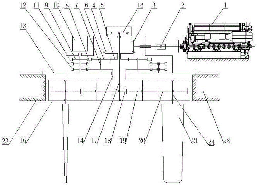
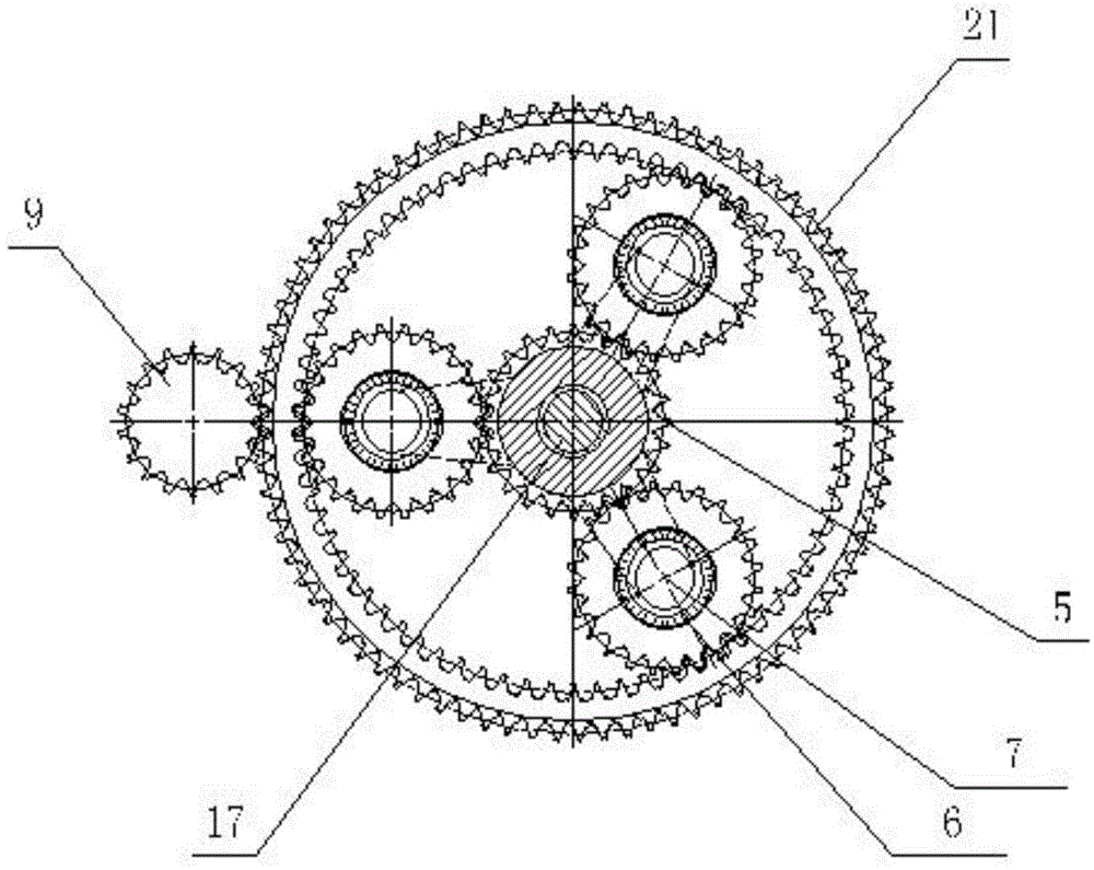
[0026] Such as figure 1 As shown, the constant-speed variable-pitch straight-wing omnidirectional propeller in this embodiment includes a coupling 2, an angle gear 3, a disc gear 4, a sun gear 5, a planetary gear 6, a planetary carrier 7, a ring gear 8, and a speed-regulating gear 9 , auxiliary power 10 (control motor), ring gear support wheel 11, planet carrier support wheel 12, machine base 13, main shaft 14, rotating disk 15, steering gear 16, rudder shaft 17, central gear 18, bridge gear 19, paddle The blade gear 20, the paddle 21 and the shaft 24, the output shaft of the main engine (diesel engine) 1 is interlocked with the angle gear 3 through the coupling 2, the angle gear 3 meshes with the disk gear 4, and the disk gear 4 is connected with the sun gear 5. move. Thus, the output shaft of the main engine (diesel engine) 1 can drive the angular ...


PUM


Abstract

The invention discloses a constant speed variable pitch straight wing all direction propeller which comprises a main engine, an engine base, a main shaft, a rotating disc, a steering engine, a rudder shaft, a central gear, an intermediate gear, a blade gear, blades and blade shafts. The main engine drives a sun gear to rotate, the sun gear is meshed with a planet gear, the planet gear is meshed with a gear ring, the gear ring is meshed with a speed control gear, and the speed control gear is controlled through auxiliary power to rotate; the planet gear is in running fit with a fixing shaft on a planet carrier, the planet carrier is linked with the rotating disc through the main shaft, and the main shaft is in running fit with the engine base; the rudder shaft sequentially penetrates through the sun gear, the main shaft and the rotating disc, one end of the rudder shaft is linked with the steering engine, and the other end of the rudder shaft penetrates through the rotating disc and then is connected with the central gear in the rotating disc; the blade shafts are in running fit with the interior of the rotating disc, the blade shafts are parallel to the main shaft, the blade shafts are evenly distributed in the circumferential direction with the central gear as a center, the blade shafts penetrate through the blade gear and are fixedly connected to the blade gear, and the blade gear is meshed with the central gear through the intermediate gear; one end of each blade shaft is connected with the corresponding blade.

Description

technical field [0001] The invention belongs to the technical field of ship propulsion and manipulation, and particularly relates to a constant-speed variable-pitch straight-wing omnidirectional propeller that can adjust the output speed of the propeller according to the sailing conditions of the ship when the main engine (diesel engine) rotates at a constant speed. . Background technique [0002] At present, most ships use the propeller-rudder system as the propulsion control device, and the propulsion control system is composed of a diesel engine, clutch, gearbox, shafting, propeller and rudder. The propeller shaft is usually arranged horizontally. The effective power from the main engine is transmitted to the propeller through the reduction gear and the shaft system, so that the propeller rotates to generate hydropower and propels the ship forward. [0003] Ships using propeller-rudder devices mainly have the following problems: [0004] 1. When the ship enters and lea...

Claims


Application Information

Patent Timeline
Patent Type & Authority Applications(China)
IPC IPC(8): B63H23/02B63H23/12
CPCB63H1/10B63H2001/105
Inventor 黄佳林陈立新
Owner ZHEJIANG FENGSHEN MARINE ENG TECH
Learn More