Eye protector for laser processing equipment

A technology of laser processing machine and pulse signal, which is applied in the direction of engineering safety devices, mechanical equipment, etc., can solve the problems of easy damage to eyes, glare and other problems, and achieve the effect of protecting eyes

Inactive Publication Date: 2006-09-06
武汉楚天激光(集团)股份有限公司
View PDF0 Cites 0 Cited by
  • Summary
  • Abstract
  • Description
  • Claims
  • Application Information

AI Technical Summary

Problems solved by technology

When the laser is processing the workpiece, it will produce dazzling light; when observing (or dire

Method used


Image

  • Eye protector for laser processing equipment
  • Eye protector for laser processing equipment
  • Eye protector for laser processing equipment

Examples


Embodiment Construction

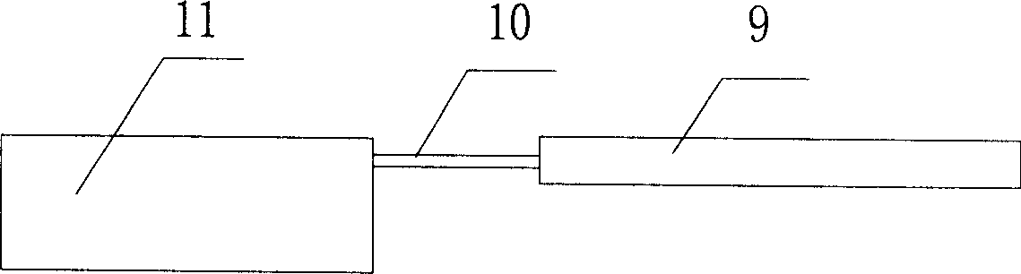
[0010] Such as figure 1 As shown, an eye protection device for a laser processing machine is mainly composed of a liquid crystal glass screen 9, a wire 10, and a pulse signal processing circuit 11. The liquid crystal glass screen 9 is connected to the output interface of the pulse signal processing circuit 11 by a wire 10 , the input interface of the pulse signal processing circuit is connected with the output end pulse signal of the laser power supply.

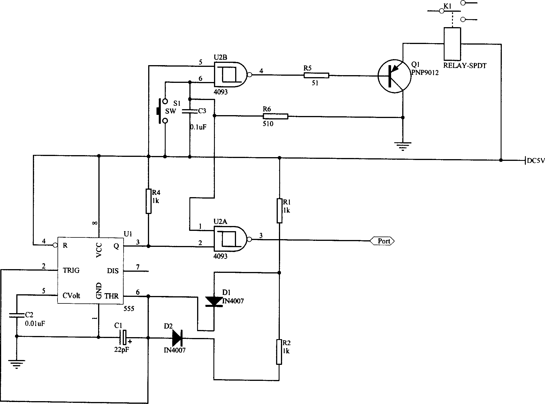
[0011] Such as figure 2 As shown, the pulse signal processing circuit is mainly composed of 555 timer, 4093 Schmitt trigger, triode Q 1 , Diode D 1 , Diode D 2 , capacitance C 1 , capacitance C 2 , capacitance C 3 , resistance R 1 , resistance R 2 , resistance R 4 , resistance R 5 , resistance R 6 , switch K 1 Composition, the 2 pins of the 555 timer are connected with the 6 pins of the 555 timer and the diode D 1 The cathode of the diode D 2 The positive pole of the 555 timer is connected to the capacitor C 2...


PUM


Abstract

The invention relates to an eye-protecting device used in laser machining device, which comprises a LCD glass screen (9), lead wires (10), and impulse signal processing circuit (11); wherein, the LCD glass screen (9) is connected to the output interface of impulse signal processing circuit (11) via lead wires (10). It is characterized in that: the input interface of said circuit is connected to the output impulse signal of laser power resource. When in working, LCD glass screen (9) is at the view that watching the laser machining process of work-piece. The invention has eye-protecting function.

Description

technical field [0001] The invention relates to an eye protection device, in particular to an eye protection device for a laser processing machine. Background technique [0002] The laser processing machine includes a base, a workbench, a bracket, a laser power supply, a laser, a light guide device, and a focusing head; the bracket is fixed on the base, and the laser is fixed on the bracket; one end of the light guide device is fixedly connected to the output end of the laser, The other end of the light guide device is fixedly connected to the focusing head; the laser light generated by the laser passes through the light guide device (or light guide system), and then is focused by the focus head and then output to process the workpiece. When the laser is processing the workpiece, it will produce dazzling light; when observing (or directly observing) the processing of the workpiece through a microscope, it is easy to damage the eyes. Contents of the invention [0003] The ...

Claims


Application Information

Patent Timeline
IPC IPC(8): F16P3/00
Inventor 孙文彭琦明张文华余其友
Owner 武汉楚天激光(集团)股份有限公司
Why Eureka
Try Eureka