Heat radiation packaging for high power LED

A LED package, high-power technology, applied in the direction of electrical components, electric solid-state devices, circuits, etc., can solve the problems of limited application of high-power LEDs, unsatisfactory heat dissipation, etc., achieve flexible use methods, increase single LED power, The effect of expanding the range of application

Inactive Publication Date: 2006-09-06
胡志国
View PDF4 Cites 19 Cited by
  • Summary
  • Abstract
  • Description
  • Claims
  • Application Information

AI Technical Summary

Problems solved by technology

[0005] To sum up, most of the current high-power LED heat dissipation packages are limited to metal sheet heat dissipation structures,

Method used


Image

  • Heat radiation packaging for high power LED
  • Heat radiation packaging for high power LED
  • Heat radiation packaging for high power LED

Examples


Embodiment 1

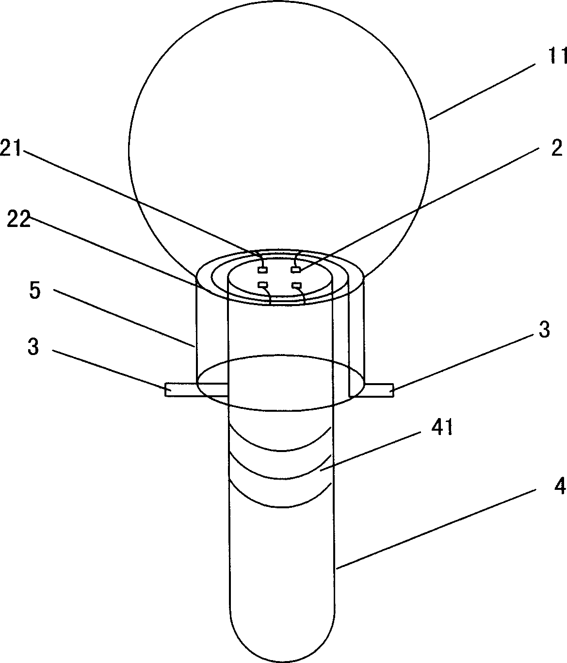
[0025] see figure 1 As shown, a heat dissipation package of a high-power LED includes an LED, and the heat generated by the LED is transferred to the external environment through a heat dissipation device connected to the LED.

[0026] The chip LED 2 is fixed on the end surface of the heat source of the heat pipe 4 by bonding or welding, and the heat pipe as a heat dissipation device also serves as a support for the LED package. An LED package cover 11 is arranged outside the chip LED, and the LED package cover is made of glass, and of course other transparent materials can also be used for the cover. A metal ring 22 is arranged outside the heat source end of the heat pipe, and the metal ring communicates with the electrode 3 , while the chip LED forms a circuit with the metal ring 22 through the gold wire 21 .

[0027] Finally, the glass cover body, the metal ring, the electrodes and the heat pipe are integrally packaged by epoxy resin 5 . In this embodiment, the chip LED i...

Embodiment 2

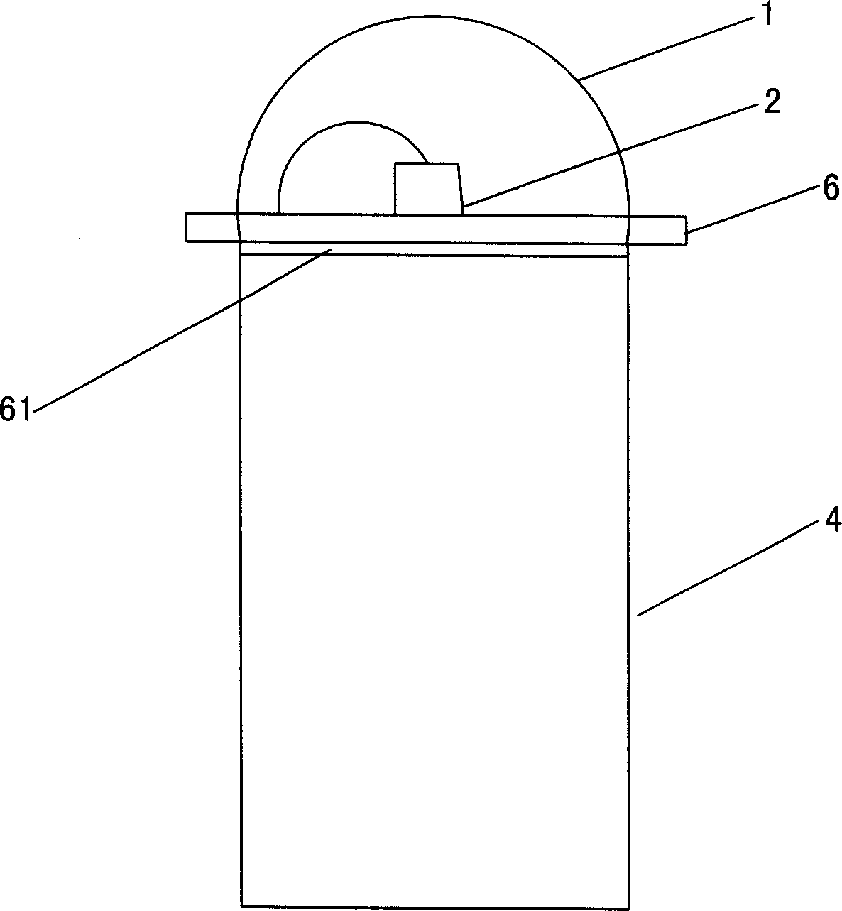
[0032] see figure 2 As shown, the difference between this embodiment and Embodiment 1 lies in that the chip LED 2 package body 1 is connected with a bracket 6 , and the bracket is connected with the heat pipe 4 for heat dissipation through a thermal conductive glue 61 .

[0033] In this embodiment, a heat pipe in a boiling heat transfer mode is used as a heat dissipation device on a conventional LED package body, which has a good heat dissipation effect and strong versatility.

Embodiment 3

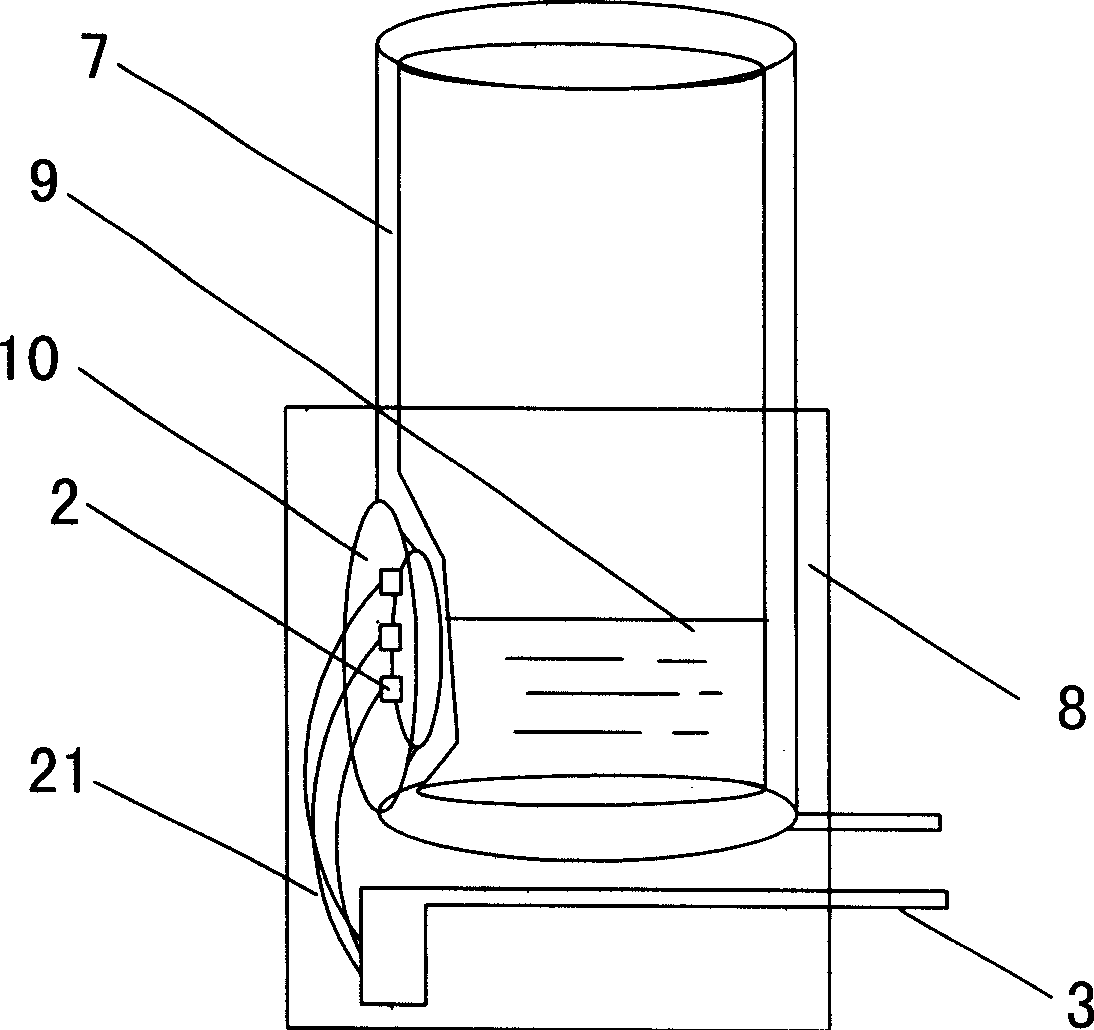
[0035] see image 3 , 4 As shown, a heat dissipation package for high-power LEDs, the heat dissipation device connected to the LED package includes an epoxy resin package base 8, and a sealed container 7 for holding a low boiling point liquid 9 is arranged in the base, and one side of the container wall is arranged There is a bowl cup 10, and the chip LED 2 is directly welded or glued to the bottom of the cup and bowl, and the chip LED is connected to the electrode 3 through a gold wire 21.

[0036] The sealed container 7 is provided with a certain degree of vacuum, and the low-boiling point liquid absorbs the heat emitted by the chip LED to vaporize to dissipate heat.

[0037] The shape of the container in this embodiment can be changed, for example, into a cuboid or other three-dimensional shapes, so as to facilitate connection with other heat dissipation devices.


PUM


Abstract

The present invention relates to high power LED heat radiation packaging technology field. It contains LED, heat sink realized adopting phase transition boiling heat transfer mode, LED packaging body adopting epoxy and heat tube integrated packaging, heat sink also capable of container having low-boiling point liquid, heat generated in LED packaging body taken by vaporizing low-boiling point liquid, heat sink also capable of adopting liquid drop impulsion. Said invention greatly raises heat transfer rate, improving LED heat-sinking capability to external environment and raising single LED packaging unit power.

Description

technical field [0001] The invention relates to a high-power LED device, in particular to a heat dissipation packaging structure capable of effectively dissipating heat generated during the operation of a light emitting diode. Background technique [0002] The semiconductor LED lighting source has the advantages of long life, energy saving, safety, green environmental protection, rich colors and miniaturization, so it is called the next-generation light source and has attracted much attention. With the update of LED diode production technology, the production technology of high-power white LED chips has matured, and the era of green lighting in which cold light sources replace incandescent lamps has arrived. [0003] High-power LED lighting equipment dissipates heat through a different heat conduction path than ordinary filament bulb equipment. Specifically, these high power LED lighting devices dissipate most of the heat through the cathode (negative side) lead or through ...

Claims


Application Information

Patent Timeline
IPC IPC(8): H01L33/00H01L23/427H01L23/34H01L33/64
CPCH01L2924/0002H01L2224/48091
Inventor 胡志国
Owner 胡志国
Why Eureka
Try Eureka