Fuel apparatus with pressurized fuel

A pressurized fuel and fuel technology, applied in lighting and heating equipment, gas fuel burners, fuel cells, etc., can solve the problems of high structure and economic costs, and achieve the effect of reducing economic costs, reducing structural costs, and simple structure

Inactive Publication Date: 2006-09-13
ROBERT BOSCH GMBH
View PDF1 Cites 0 Cited by
  • Summary
  • Abstract
  • Description
  • Claims
  • Application Information

AI Technical Summary

Problems solved by technology

The disadvantage in this case, however, is that such units require high structural and economic outlay

Method used


Image

  • Fuel apparatus with pressurized fuel
  • Fuel apparatus with pressurized fuel
  • Fuel apparatus with pressurized fuel

Examples


Embodiment Construction

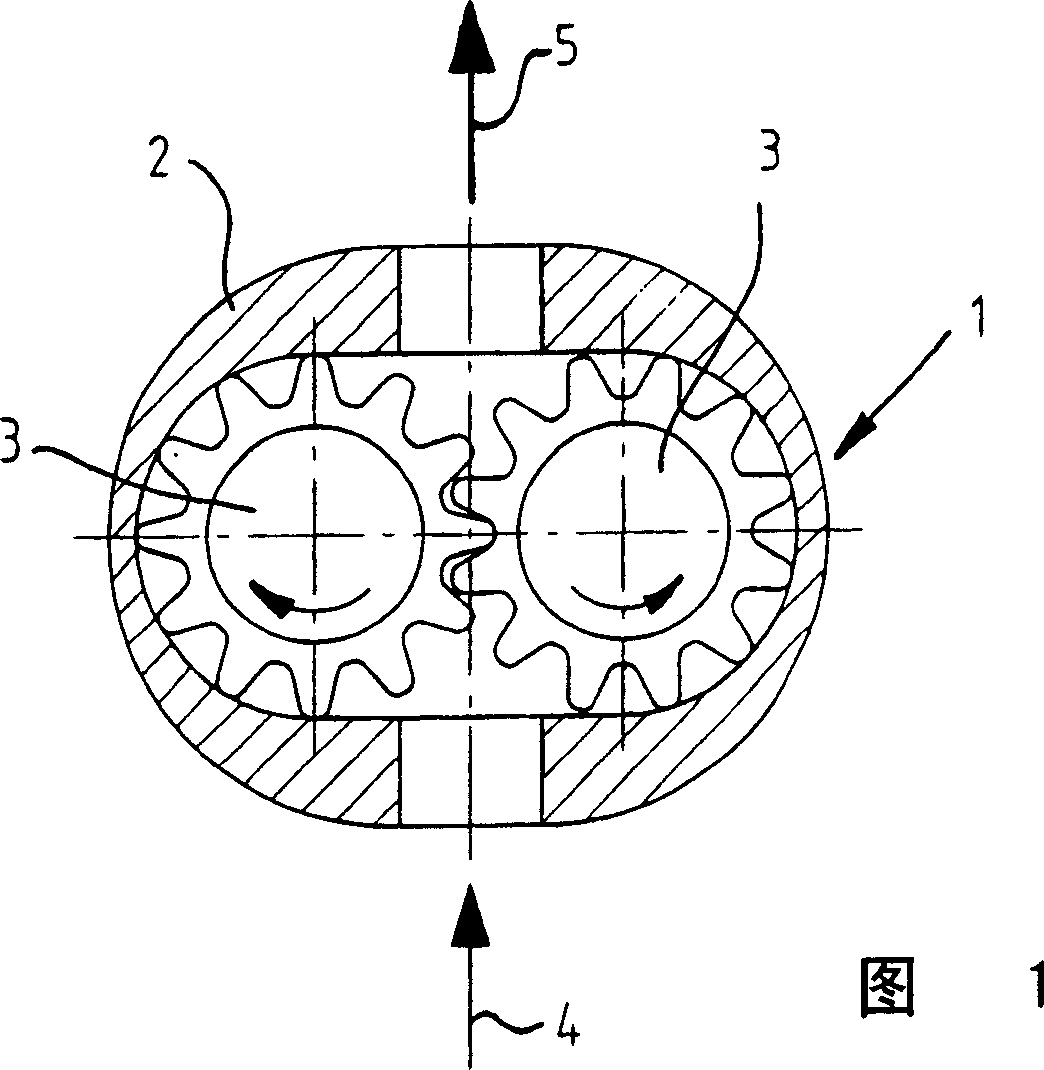
[0032] In FIG. 1, a gear mechanism 1 with a housing 2 and two meshing gears 3 is schematically shown. The gear mechanism 1 has a high-pressure side inlet 4 and a low-pressure side outlet 5.

[0033] When the gear mechanism 1 uses fuel or hydrogen to flow, the gear 3 rotates in the direction of the arrow shown in the figure.

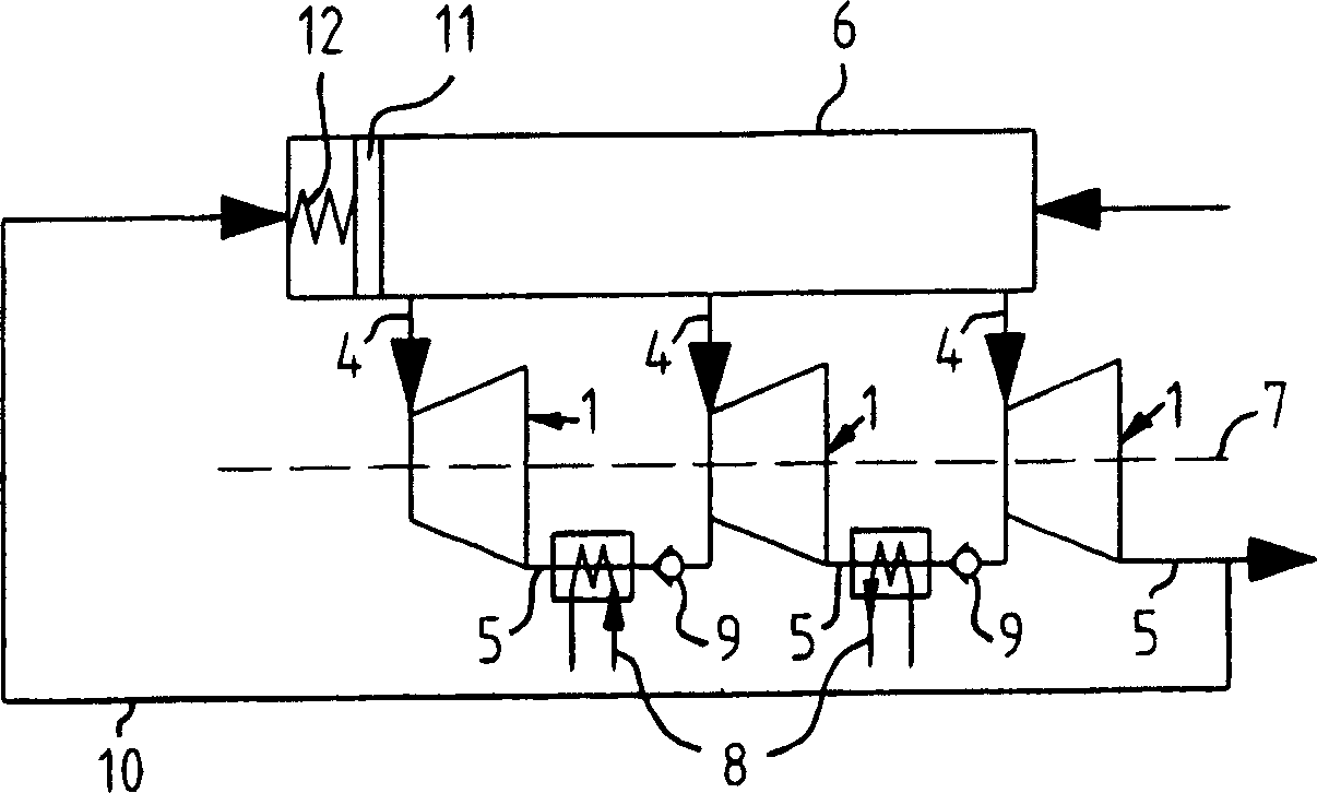
[0034] in figure 2 Shown in is a schematic representation of a gear mechanism system with multi-stage pressure expansion. Here, the distribution unit 6 distributes the fuel to, for example, three gear mechanisms 1 arranged on a common transmission shaft 7. In order to generate electrical energy, the drive shaft 7 can be connected to a generator, which is not shown in detail.

[0035] In order to add heat to the fuel or hydrogen cooled due to expansion, a heat exchanger 8 or a heating unit 8 may be arranged between the gear mechanism 1 respectively. This can promote the cooling of individual components, such as the cooling of high-power electronic components, ...


PUM


Abstract

The fuel system has pressure energy utilization unit, which is formed as gear machine (1) with two gear wheels (3), shifted in motion by the fuel flowing against it and are interlocked, for production of mechanical energy.

Description

Technical field [0001] The present invention relates to a fuel device with a fuel cell unit and / or an internal combustion engine according to the preamble of claim 1, wherein a fuel device for delivering pressure-loaded fuel to the fuel cell unit and / or internal combustion engine is provided Supply device. Background technique [0002] Through public discussions on new vehicle driving devices that reduce emissions, such as zero-emission vehicles (ZEV), protection of fossil resources, etc., interest in hydrogen as a future energy carrier has increased significantly. Hydrogen can be converted either in an internal combustion engine or in a fuel cell, for example. In the fuel cell, chemical compound energy is directly converted into electrical energy, which is again converted into mechanical driving energy by means of an electric motor. [0003] In principle, hydrogen has renewable production, no harmful substances and no CO 2 Possibility of burning or conversion. In addition, other...

Claims


Application Information

Patent Timeline
Patent Type & Authority Applications(China)
IPC IPC(8): H01M8/04H01M8/06H01M8/00F01D15/00F01K25/00F02C1/00F02C3/22F02C6/00F02M21/02F23D14/28B60K1/04
CPCY02E60/50H01M8/04089H01M2250/407H01M2250/20Y02T90/32Y02E60/563Y02T90/40
Inventor P·萨茨格尔R·萨利格尔
Owner ROBERT BOSCH GMBH
Why Eureka
Try Eureka