
Casting mold device and method producing cast

A manufacturing method and casting technology, applied in the field of casting mold devices, can solve problems such as inability to cut off, molten metal flowing out, and molten metal not being sufficiently solidified.

Inactive Publication Date: 2006-09-20
MAZDA MOTOR CORP
View PDF2 Cites 11 Cited by
  • Summary
  • Abstract
  • Description
  • Claims
  • Application Information

AI Technical Summary

Problems solved by technology

However, the molten metal is not sufficiently solidified in the riser formed on the upper part of the sand mold, so if the posture is changed, unsolidified molten metal may flow out.
And by changing the posture, the shape of the riser portion will change, and when the riser portion is positioned and cut off, the inconvenience of not being able to perform a stable cutting operation occurs.

Method used


Image

  • Casting mold device and method producing cast
  • Casting mold device and method producing cast
  • Casting mold device and method producing cast

Examples


Embodiment Construction

[0040] Specific embodiments of the present invention will be described below.

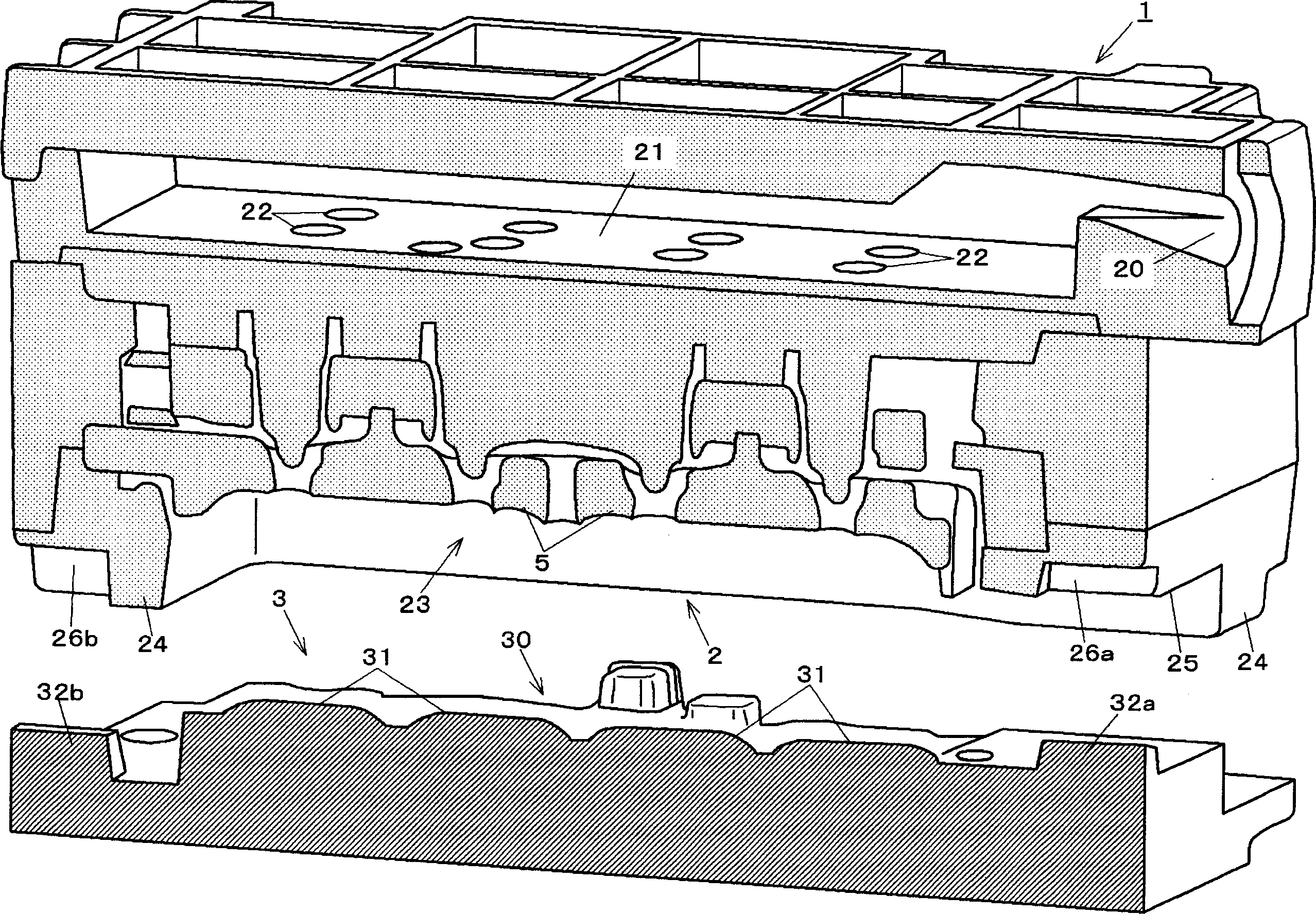
[0041] Such as figure 1 As shown, the casting mold device 1 of the present embodiment is used for casting the cylinder head of the engine, and it has: an upper mold 2 composed of a plurality of sand molds; a metal lower mold 3; The die cavity 4 (referring to Figure 5 Cores 5...5 for the cooling water jacket in ); cores 6...6 for the suction port and exhaust port (refer to Image 6 ). The molten metal of aluminum alloy is filled into cavity 4 to form casting 7 (referring to Figure 5 ).

[0042] On the upper die 2 made of a sand mold, there are formed: a gate 20 located on the upper side for injecting the aluminum alloy melt as a light alloy melt; a riser 21 communicating with the gate 20 at the upper part; The riser portion 21 communicates with the mold cavity 4 with a plurality of runners 22 . . . 22 . Furthermore, the upper mold 2 has an opening 23 forming the cavity 4 . Further, a perip...


PUM


Abstract

The invention provides a casting mold device and a method for manufacturing castings using the casting mold device. The casting mold device includes a metal mold and a sand mold (2), wherein the sand mold has: a riser formed on the opposite side of the metal mold. One side; the opening (25), which is sealed by a metal mold to form a mold cavity when forming a mold; The surface of the surrounding wall protrudes more toward the metal mold side, wherein a notch is provided on the surrounding wall to make the inner part (S) of the surrounding wall communicate with the outer part. The casting method includes the following steps: a molding process, The sand mold and the metal mold are combined to form a mold cavity; the casting process is to pour molten metal into the mold cavity; the mold opening process is to leave the casting (7) on one side of the sand mold and separate the sand mold from the metal mold; and In the cooling step, the sand mold with the casting left is immersed in a cooling tank with the opening side positioned on the lower side. With this method, when the sand mold and casting are immersed in cooling water in the cooling process, air bubbles (X) remaining in the inner portion (S) are discharged through the notch portion (25), and cooling or quenching can be efficiently performed.

Description

technical field [0001] The present invention relates to a casting mold device combining a metal mold and a sand mold and a casting method using the casting mold device. Background technique [0002] Conventionally, methods of forming a casting mold device by combining a metal mold and a sand mold, and performing casting using this are well known. Such a molding device is the one disclosed in Japanese Patent No. 3068185. This publication shows that if this device is used, when the molten metal is poured into the mold cavity formed in the mold device, the molten metal in solidification is quickly and continuously removed by the metal mold constituting the mold device. The solidifying molten metal creates large thermal gradients and directional solidification of the entire casting is achieved. [0003] In addition, since the above-mentioned thermal gradient is generated, compared with the casting method using a sand mold, the casting method usi...

Claims


Application Information

Patent Timeline
IPC IPC(8): B22C9/00
Inventor 山本直彰富谷孝二长藤则政青田严
Owner MAZDA MOTOR CORP
Learn More