'V' type builti-in rotor of permanent megnet dynamo

A permanent magnet motor, built-in technology, applied in the direction of magnetic circuit rotating parts, magnetic circuit shape/style/structure, etc., to achieve the effect of increasing reactive reactance, reducing weight, and reducing iron loss

Inactive Publication Date: 2006-09-20
SHANGHAI UNIV
View PDF0 Cites 24 Cited by
  • Summary
  • Abstract
  • Description
  • Claims
  • Application Information

AI Technical Summary

Problems solved by technology

The mutual constraints among the rotor magnetic circuit structure of the motor, electromagnetic radial force wave, rotor centrifugal stress and thermal stress, air gap eccentricity caused by the rotor support system, and the mechanical properties of the rotor silicon steel sheet limit the maximum safe operating speed of the built-in rotor motor. improve

Method used


Image

  • 'V' type builti-in rotor of permanent megnet dynamo
  • 'V' type builti-in rotor of permanent megnet dynamo

Examples


Embodiment Construction

[0025] The "V" type built-in rotor structure of the permanent magnet motor of the present invention will be further described in detail in conjunction with the accompanying drawings and specific implementation examples:

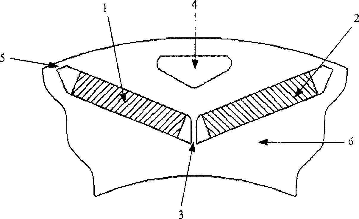
[0026] see figure 2 In the "V" type built-in rotor of the permanent magnet motor, the lower permanent magnet poles of each pole are composed of two permanent magnets (1, 2) with the same shape and the same polarity embedded in the rotor core (6 ), the iron core part in the middle of the two permanent magnets (1, 2) is a reinforcing rib (3), and an auxiliary hole (4) is arranged directly above the reinforcing rib (3).

[0027] The polar arc coefficient of the permanent magnet and the angle between the permanent magnets and the size of the magnetic isolation bridge (5) and the rib (3) need to be analyzed by means of finite element analysis software for coupling simulation analysis of the motor magnetic field and the stress field, and try to make the opposite e...


PUM


Abstract

The invention converts built-in type rotor structure in conventional 'I'type to built-in type rotor structure in 'V'type, as well as sets up reinforced ribs between magnetic poles and sets up accessory pores above the said reinforced ribs. Changing distribution of deformation on surface of rotor diameter, the rotor structure in 'V'type makes maximal centrifugal stress point shift to reinforced ribs of rotor. The maximal centrifugal stress point is tensile stress restricted by tensile strength of material of rotor core. Since tensile strength of material of rotor core is larger than yield strength, thus, operating mechanical property of rotor at high speed is enhanced remarkably. Moreover, the said accessory pores can control waveform of air gap field, lightens weight of rotor, reduces centrifugal force, vibration and noise as well as improves operating mechanical property and other performances of motor.

Description

technical field [0001] The invention relates to a rotor of a permanent magnet motor, in particular to a "V" type built-in rotor of a permanent magnet motor. Background technique [0002] There are various rotor structures of permanent magnet motors. As a whole, the most commonly used types are Surface Mounted Permanent Magnet (SPM for short) rotor structure and Interior Permanent Magnet (IPM for short) rotor structure. [0003] The design of the built-in rotor permanent magnet motor strives to pursue a small air gap and a small gap magnetic isolation bridge to increase the reluctance torque component to achieve maximum torque / current control at the base speed point and maximum power field weakening control at the highest speed point. However, when operating under maximum peak torque and high-speed conditions, due to strong magnetic circuit saturation and deep field-weakening control, the air-gap magnetic field waveform of the motor is seriously distorted, and its radial comp...

Claims


Application Information

Patent Timeline
Patent Type & Authority Applications(China)
IPC IPC(8): H02K1/27
Inventor 黄苏融张琪谢国栋
Owner SHANGHAI UNIV
Why Eureka
Try Eureka