Synchronous motor

A technology for synchronous motors and stator cores, applied to synchronous motors with stationary armatures and rotating magnets, electric components, electromechanical devices, etc., can solve the problems of not interfering with the rotor, difficult wiring of the external wiring of the coil, etc., and achieve simplified assembly Process, prevention of rotor interference, and productivity improvement effects

Inactive Publication Date: 2006-09-20
小松 文人
View PDF4 Cites 5 Cited by
  • Summary
  • Abstract
  • Description
  • Claims
  • Application Information

AI Technical Summary

Problems solved by technology

[0008] In addition, the external wiring of the coil needs to be carried out in the narrow space surrounded by the rotor, and it is difficult to wire the external wiring of the coil without interfering with the rotor

Method used


Image

  • Synchronous motor
  • Synchronous motor
  • Synchronous motor

Examples


Embodiment Construction

[0046] Hereinafter, the best mode for carrying out the invention will be described in detail with reference to the drawings.

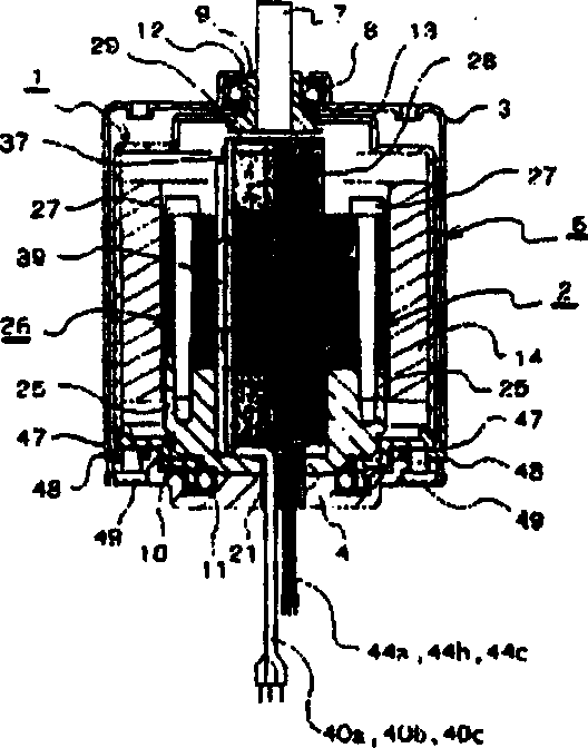
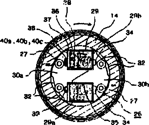
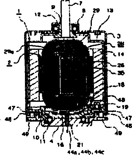
[0047] Hereinafter, a two-pole synchronous motor will be described as an example of an outer rotor type synchronous motor. First, refer to Figure 1 to Figure 9 The overall configuration of the 2-pole synchronous motor of the first configuration will be described.

[0048] Figure 1A Among them, the rotor 1 and the stator 2 are accommodated in the casing 6 which is formed by stacking the upper casing 3 and the lower casing 4 up and down and is threaded and stopped by the stop screw 49 . An output shaft 7 is fitted into the upper case 3 . The output shaft 7 is pivotally supported by the upper bearing 8 fitted in the upper case 3 so that the sleeve portion 9 is rotatable.

[0049] In the rotor 1 , a rotor base member 10 is integrally fitted, and the rotor base member 10 is rotatably supported by a lower bearing 11 fitted into the lower housing 4 . As t...


PUM


Abstract

The invention provides a synchronous motor in which the share of space for a coil winding wound on a stator core through a bobbin is improved. A stator core (26) is dividably assembled to the axial opposite sides of a bobbin (29) having a coil winding (28) wound thereon.

Description

technical field [0001] The present invention relates to synchronous motors. Background technique [0002] In recent years, direct current (DC) or alternating current (AC) fan motors for cooling are installed in, for example, OA equipment, and 2-pole or 4-pole AC fan motors are especially suitable for equipment requiring high rotational speed. [0003] Next, the composition of such an AC fan motor will be described. That is, there is a synchronous motor in which a rectifier circuit connected to a coil winding has a diode, a brush, and a converter, rectifies an AC current supplied from an AC power source, and rotates a rotor to conduct electricity to start operation as a DC motor. The rotation of the rotor rises to the vicinity of synchronous rotation, and at this point, the converter is mechanically separated from the rectification circuit, and switched to synchronous operation using an AC power supply (refer to Patent Document 1 (Japanese Patent Laid-Open Publication No. He...

Claims


Application Information

Patent Timeline
Patent Type & Authority Applications(China)
IPC IPC(8): H02K1/18H02K1/14H02K3/32H02K5/22H02K21/22H02K29/08
CPCH02K5/225H02K3/325H02K29/08H02K1/14H02K1/187H02K21/22Y10T29/49009H02K1/185H02K5/1732H02K29/10H02K29/12H02K1/18
Inventor 小松文人
Owner 小松 文人
Why Eureka
Try Eureka