Sound matching body, process for producing the same, ultrasonic sensor and ultrasonic wave transmitting/receiving system
A manufacturing method and ultrasonic technology, which are applied in directions such as direction finders, sensors, and sensor types that use ultrasonic/sonic/infrasonic waves, and can solve problems such as easy breakage of ends and difficulty in achieving thickness.
- Summary
- Abstract
- Description
- Claims
- Application Information
AI Technical Summary
Problems solved by technology
Method used
Image
Examples
Embodiment approach 1
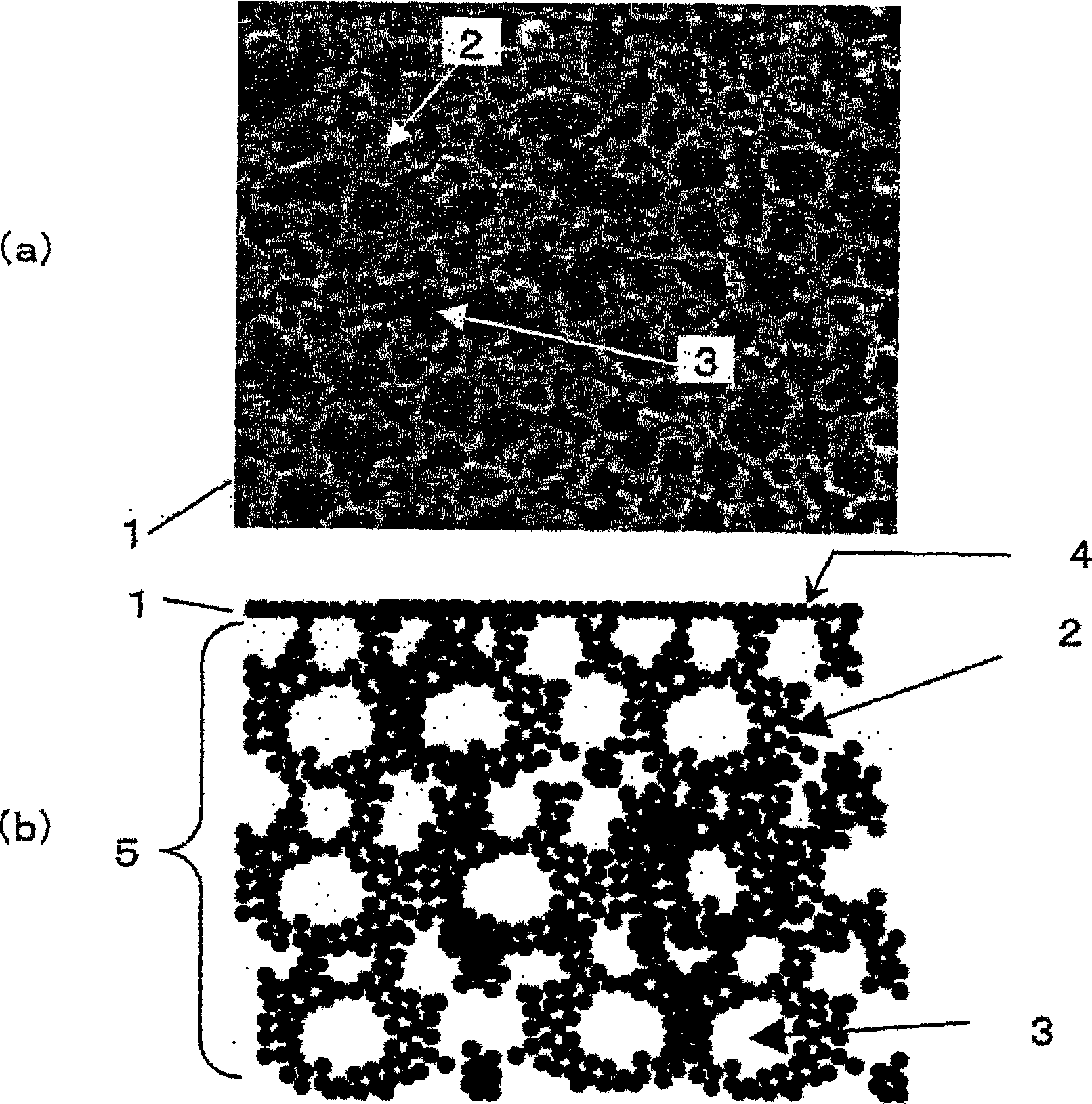
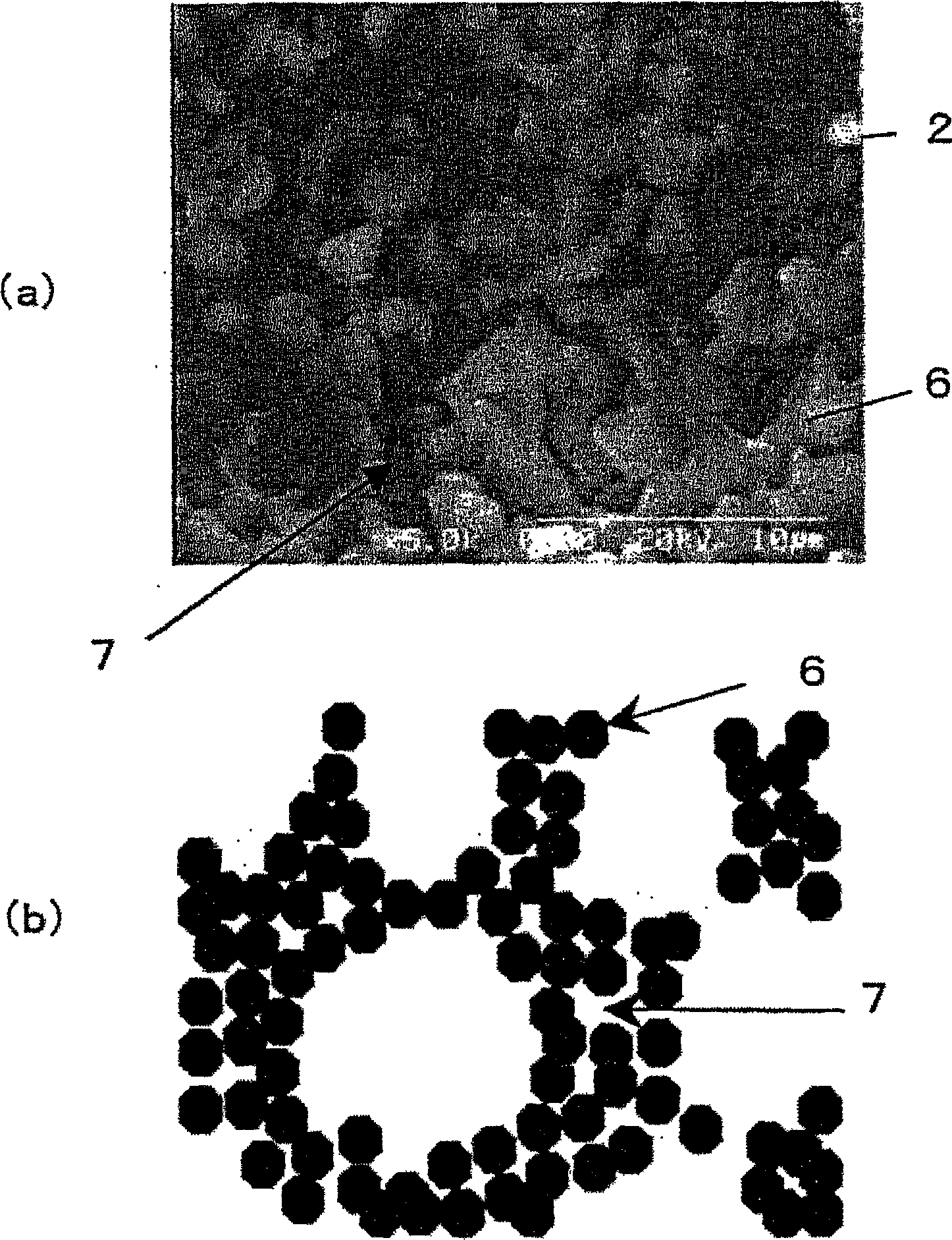
[0074] As Embodiment 1 of the present invention, an acoustic matching body composed of a specific ceramic porous body will be described. figure 1 Among them, (a) is a photomicrograph showing the cross section of the ceramic porous body constituting the acoustic matching body of the present invention, and (b) is a schematic diagram showing the cross section of the ceramic porous body constituting the acoustic matching body of the present invention. figure 1 Among them, 1 denotes a ceramic porous body (acoustic matching body), 2 denotes a ceramic matrix, 3 denotes pores defined by the ceramic matrix 2, 4 denotes a surface layer, and 5 denotes an inner layer. figure 2 It is an enlarged view of a part of the ceramic matrix 2 , (a) is a micrograph of an enlarged cross section of the ceramic matrix, and (b) is a schematic diagram showing an enlarged cross section of the ceramic matrix. figure 2 Among them, 6 represents ceramic particles, and 7 represents voids between ceramic pa...
Embodiment approach 2
[0103] Image 6 In (a), as Embodiment 2 of the present invention, an acoustic matching body of a composite structure is shown, Image 6 (b) shows an ultrasonic sensor in which the acoustic matching body is used as an acoustic matching layer. Image 6 The acoustic matching body 44 shown in (a) is a disc shape with a diameter of 10.8 mm and a thickness of 1.8 mm, and has a composite structure as follows. The concave portion of the first porous body 42 is filled with the second porous body 43 .
[0104] Image 6 In (a), although the first porous body 42 is shown as a structure having a ceramic matrix 41 as a skeleton, and the pores 40 are defined by the ceramic matrix 41, the voids between ceramic particles are formed in the ceramic matrix 41. Situation such as reference figure 1 as stated. In addition, the ceramic porous body 42 is the same as the porous body of Embodiment 1, and is a gel-like porous molded body obtained by gelling a bubble-containing ceramic slurry of a c...
Embodiment approach 3
[0116] Figure 8 In the figure, the method of manufacturing the acoustic matching body of a composite structure is shown schematically as Embodiment 3 of this invention. Figure 8 It shows the state where the first porous body 42 formed with the recess 63 for disposing the second porous body inside is placed in the molding die 61 with the recess 63 facing down, and is accommodated in the container 62 . In order to distinguish the forming die 61 used here from the forming die used for forming the first porous body 42, in this specification, for convenience, the forming die for forming the second formed body is sometimes referred to as the second forming die, The molding die for forming the first molded body is referred to as a first molding die. Thus, the molding die 61 is the second molding die. The container 62 is filled with the Figure 7 The starting material solution 64 prepared in step 51 is shown. When the molding die 61 is immersed in the solution 64 , the solution ...
PUM
| Property | Measurement | Unit |
|---|---|---|
| density | aaaaa | aaaaa |
| density | aaaaa | aaaaa |
| diameter | aaaaa | aaaaa |
Abstract
Description
Claims
Application Information
 - R&D
- Intellectual Property
- Life Sciences
- Materials
- Tech Scout
- Unparalleled Data Quality
- Higher Quality Content
- 60% Fewer Hallucinations
Browse by: Latest US Patents, China's latest patents, Technical Efficacy Thesaurus, Application Domain, Technology Topic, Popular Technical Reports.
© 2025 PatSnap. All rights reserved.Legal|Privacy policy|Modern Slavery Act Transparency Statement|Sitemap|About US| Contact US: help@patsnap.com


