
Hologram recorder

A technology for recorders and holographic recording media, applied in the field of holographic recorders, which can solve the problems of harsh optical system design conditions, increasing the number of effective pixels, increasing distances, etc.

Inactive Publication Date: 2006-10-04
FUJITSU LTD
View PDF1 Cites 8 Cited by
  • Summary
  • Abstract
  • Description
  • Claims
  • Application Information

AI Technical Summary

Problems solved by technology

[0004] However, as will be described in detail in the following paragraphs, there is a problem in the conventional hologram in that as the number of effective pixels of the spatial light modulator 500 increases, the design conditions for the optical system including, for example, the objective lens become more and more demanding
[0007] Although not specifically shown, there may be another case in which the pixel pitch is reduced without changing the entire pixel area of ​​the spatial light modulator, so as to be consistent with Figure 4 Compared with the case in , the number of effective pixels relative to the recording beam is increased
Also in this case, the result is an increase in the distance between the optical axis and the ±1st order diffraction due to the increase in the diffraction angle with the pixel pitch at the exit surface of the spatial light modulator
This means that even if the pixel pitch is reduced, the effective aperture of the objective must be increased even more

Method used


Image

  • Hologram recorder
  • Hologram recorder
  • Hologram recorder

Examples


Embodiment Construction

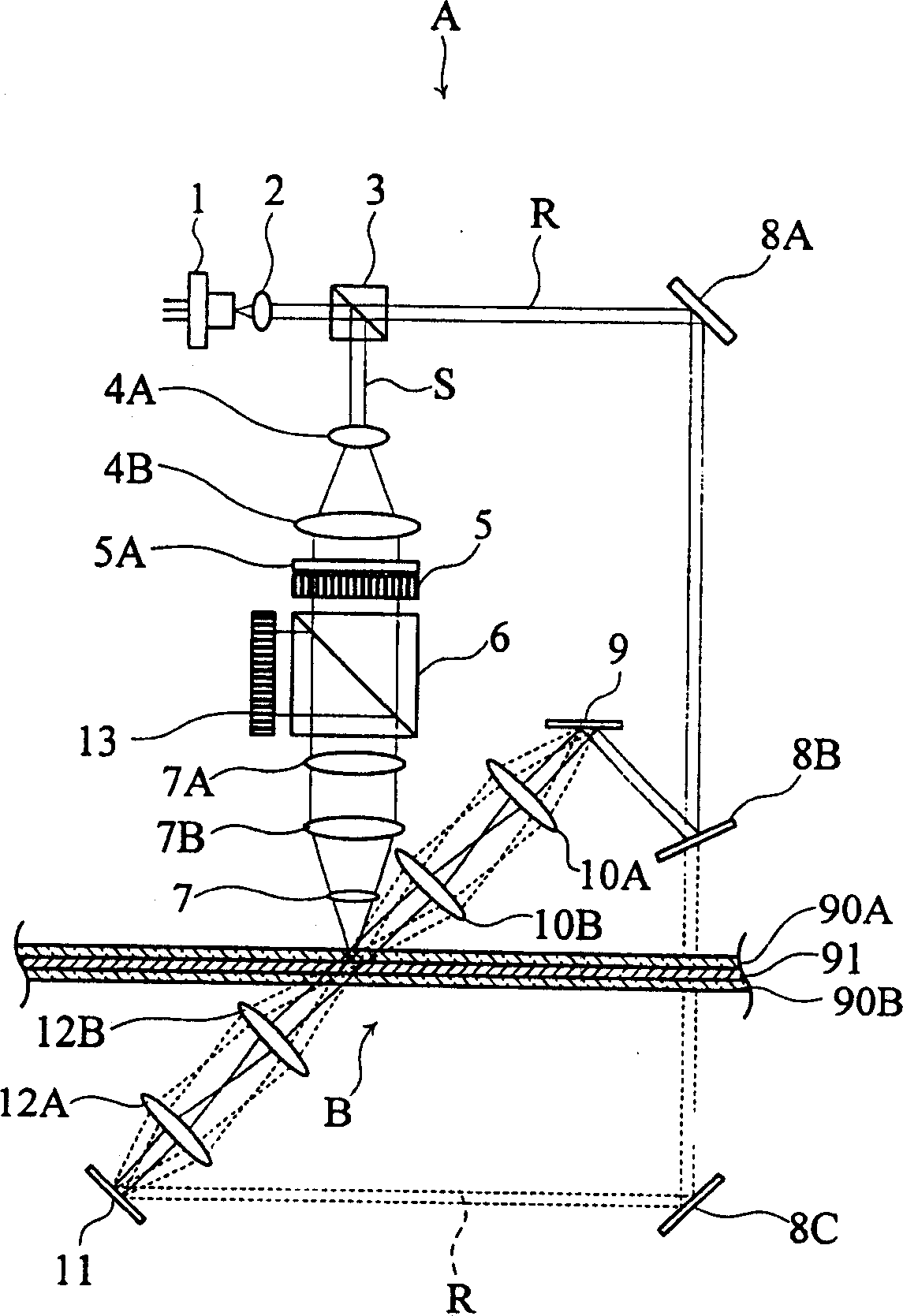
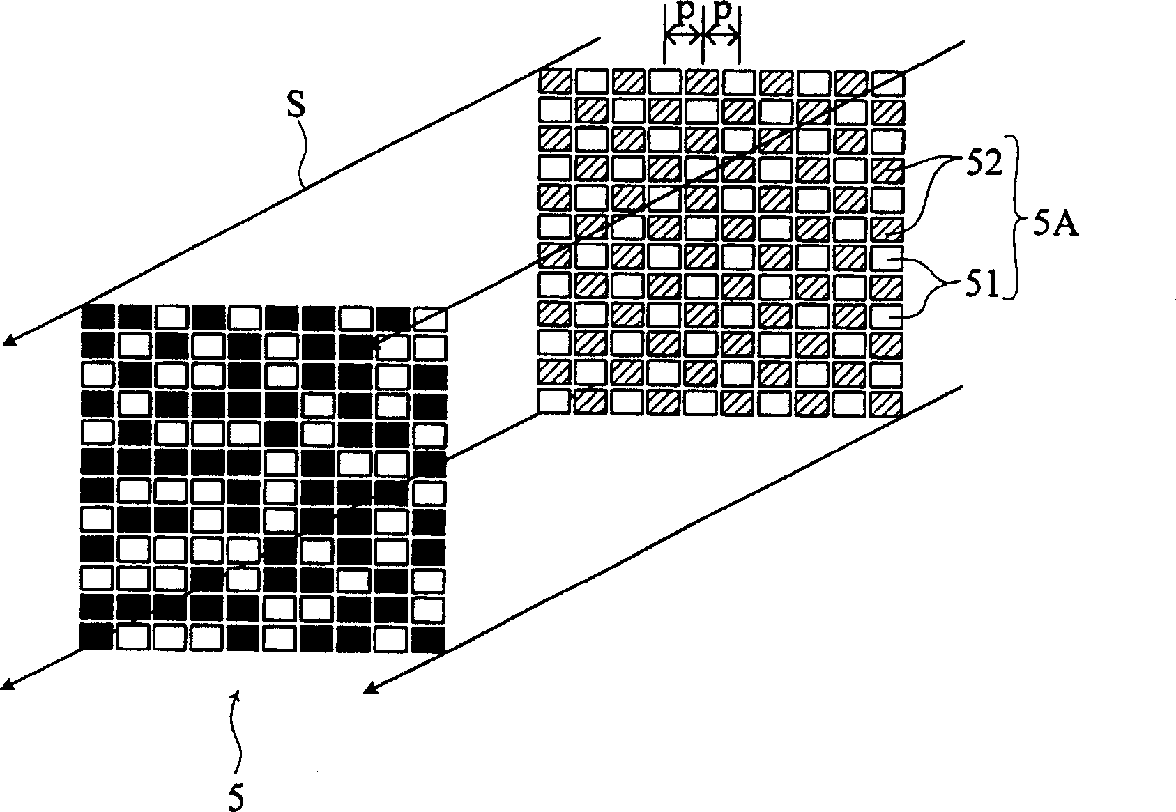
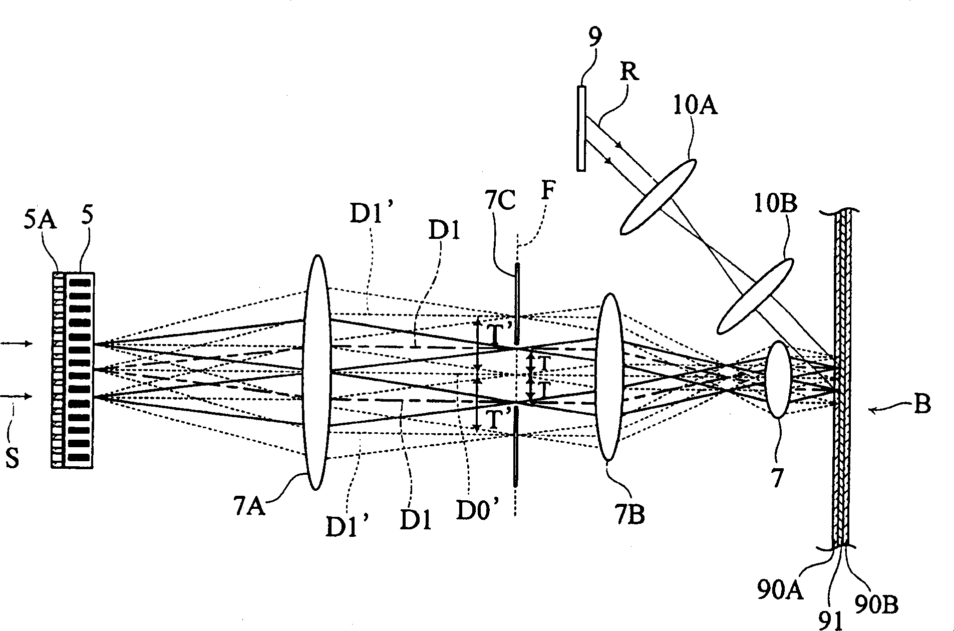
[0021] Hereinafter, preferred embodiments of the present invention will be specifically described with reference to the accompanying drawings. Figures 1 to 3 A hologram is shown as an embodiment of the present invention.

[0022] Such as figure 1 As shown, the holographic recorder A according to this embodiment includes a light source 1, a collimating lens 2, a first beam splitter 3, a beam expander 4A, 4B, a phase shift mask 5A, a spatial light modulator 5, a second beam splitter Beamer 6, relay lenses 7A, 7B, objective lens 7, fixed mirrors 8A, 8B, 8C, recording galvanometer mirror 9, recording condensing lenses 10A, 10B, reproduction galvanometer mirror 11, reproduction condensing lenses 12A, 12B , and photodetector 13. Other elements not shown include a rotation mechanism that rotates the hologram recording medium B as a rotary disk, and a carrying mechanism that moves an optical system such as the objective lens 7 in the radial direction of the hologram recording medi...


PUM


Abstract

A hologram recorder is provided for recording a hologram on a hologram recording medium by interference of a recording beam with a reference beam. The recorder includes a light source for outputting coherent light to be split into the recording beam and the reference beam; a spatial light modulator for modulating the recording beam into a form representing information to be recorded; an objective lens for outputting the recording beam; and a phase shift mask provided at a light entering surface of the spatial light modulator. The mask is configured to allow the recording beam to pass through, and also to partially shift the phase of the recording beam passing through the mask.

Description

technical field [0001] The present invention relates to a hologram for recording holograms in a holographic recording medium. Background technique [0002] A conventional hologram is disclosed in, for example, JP-A-2002-216359. This holographic recorder has such Figure 4 The basic structure shown. Specifically, a laser beam emitted by a laser source (not shown) is divided into a recording beam S and a reference beam R. Referring to FIG. Next, the recording beam S is modulated by the spatial light modulator 500A into a form representing the information to be recorded, and then passes through the relay lenses 700A, 700B and then the objective lens 700 before it reaches the recording layer 91 of the holographic recording medium B. On the other hand, reference beam R is directed to holographic recording medium B by recording galvanometer mirror 900 and condenser lenses 100A, 100B, and intersects recording beam S on recording layer 91 of holographic recording medium B. As a r...

Claims


Application Information

Patent Timeline
Patent Type & Authority Applications(China)
IPC IPC(8): G11B7/0065G11B7/135G11B7/125G03H1/22
CPCG03H2225/55G03H1/04G03H2223/13G11B7/0065G03H1/265G11B7/128G11B7/1381G11B7/1367H04M1/23G06F3/0233G06F3/018
Inventor 吉川浩宁手塚耕一宇野和史
Owner FUJITSU LTD
Learn More