Electrostatic atomizer and its cleaning method
An electrostatic coating and cleaning solution technology, applied in the direction of electrostatic spraying devices, spraying devices, liquid supply devices, etc., can solve the problems of increasing characteristics and reducing characteristics slowly, paint consumption, etc., to improve responsiveness, reduce waste, Effect of suppressing unnecessary spray
- Summary
- Abstract
- Description
- Claims
- Application Information
AI Technical Summary
Problems solved by technology
Method used
Image

Examples
Embodiment 1
[0045] Example 1 ( Figure 1 to Figure 6 )
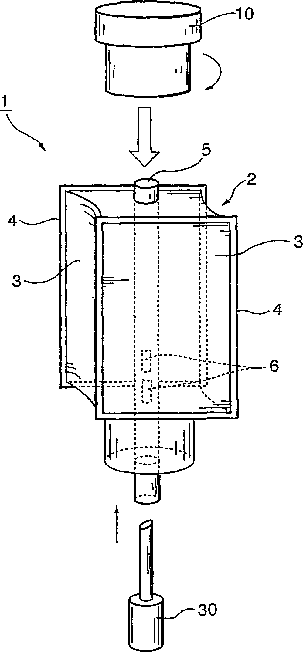
[0046] figure 1 Indicates a cartridge paint tank assembly 1 that can be installed on an electrostatic paint coater. The illustrated paint tank assembly 1 includes a flexible paint bag 2 as a paint container for storing paint. The paint bag 2 has a substantially rectangular parallelepiped outline shape, and has a relatively rigid rectangular frame 4 on a pair of side walls 3 facing each other. At least two end walls of the paint bag 2 and the other two walls other than the pair of side walls 3 corresponding to the rectangular frame 4, that is, the two side walls facing each other extending between the pair of frames 4 and 4 are relatively soft. material, whereby a pair of frames 4, 4 can approach each other. The soft side wall 3 of the paint bag 2 can be protected from erosion by thinner (paint solvent) if it is water-based paint or oil-based paint by laminating polypropylene, fluorocarbon resin, etc. on a metal sheet made of alu...
Embodiment 2
[0069] Example 2 ( Figure 7 , Figure 8 )
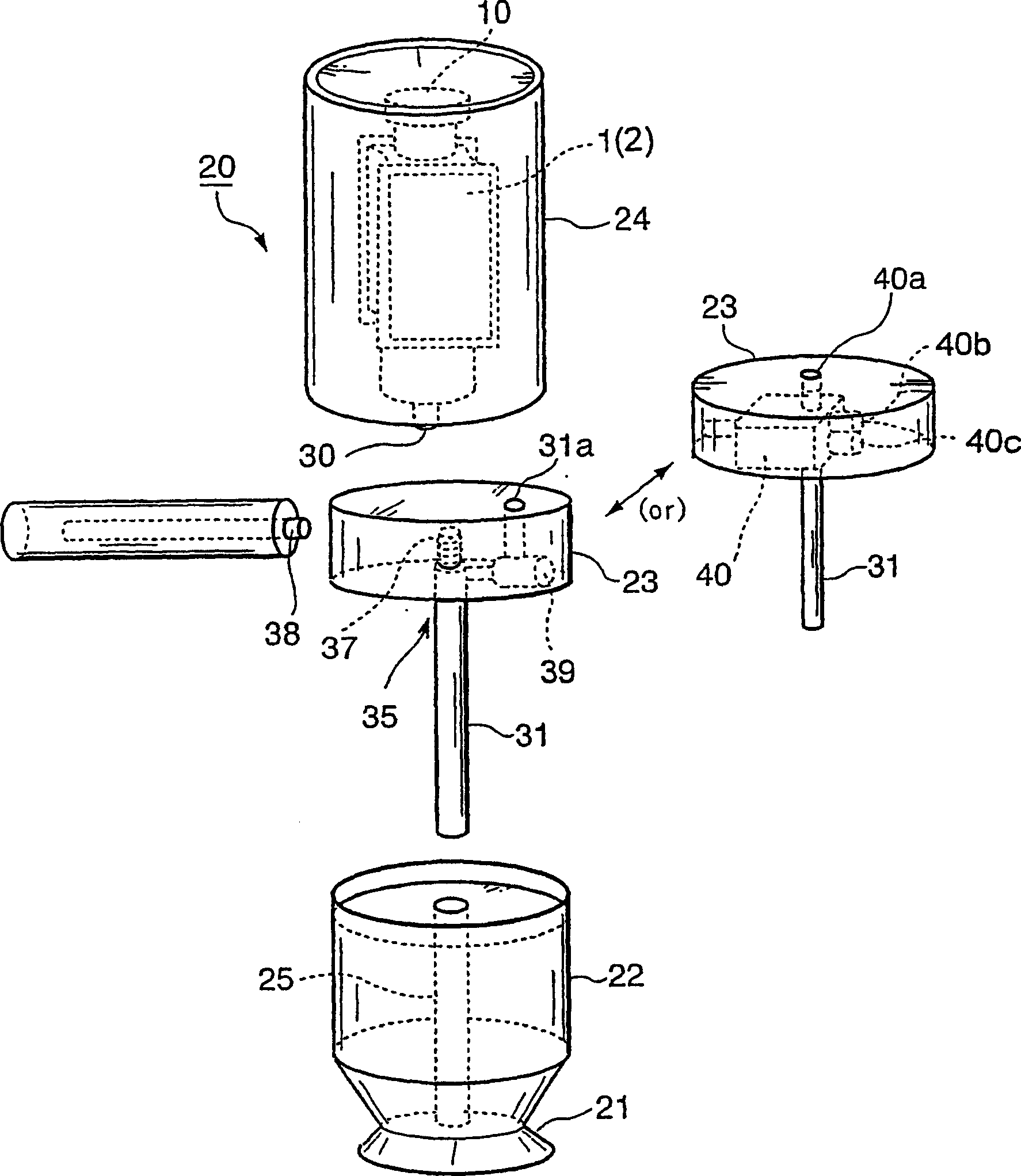
[0070] When it is necessary to change the color or the paint of the paint bag 2 is used up, the above-mentioned embodiment 1 is to replace the paint box assembly 1 including the paint bag 2, but in this embodiment 2, the tank body 24 is replaced of. That is, if Figure 7 As shown, the tank body 24 containing the paint tank assembly 1 including the paint bag 2 can be connected to the pump part 23 of the coating machine 20 including the atomization generation part 22 and the pump part 23 through the automation system outside the figure. Removable. When the color needs to be changed or the paint in the paint bag 2 is used up, the tank body 24 is unloaded from the coating machine 20 , and a new tank body 24 is installed on the pump part 23 of the coating machine 20 .
[0071] In the tank body 24, for example, a check valve or an on-off valve 52 ( Figure 7 , Figure 8 ). The operation of refilling the empty tank body 24 (paint b...
Embodiment 3
[0073] Embodiment 3 ( Figure 9 )
[0074] In the above-mentioned Embodiments 1 and 2, the coating machine that supplies the paint from the tank body 24 to the single bell cup 21 is illustrated, but it can also be used as Figure 9 As shown, paint is supplied from a single tank 24 to two or more bell cups 21 . Figure 9 The illustrated dual head coater has 2 heads. The two heads each have a pump unit 23 and an atomization generating unit 22 , and paint is supplied to each pump unit 23 through paint supply passages 55A and 55B branched from a paint outlet 50 of a single tank body 24 into two branches. Figure 9 The shown reference numeral 56 denotes a cleaning gate valve, and when the color is changed, the cleaning gate valve 56 is opened to introduce cleaning liquid such as thinner into the internal paint passage of the coating machine 20 from the outside. Figure 9 The shown reference numeral 57 denotes a motor coupling, and 58 denotes a cleaning sleeve.
[0075] For Exam...
PUM
 Abstract
Description
Claims
Application Information
 - R&D
- Intellectual Property
- Life Sciences
- Materials
- Tech Scout
- Unparalleled Data Quality
- Higher Quality Content
- 60% Fewer Hallucinations
Browse by: Latest US Patents, China's latest patents, Technical Efficacy Thesaurus, Application Domain, Technology Topic, Popular Technical Reports.
© 2025 PatSnap. All rights reserved.Legal|Privacy policy|Modern Slavery Act Transparency Statement|Sitemap|About US| Contact US: help@patsnap.com