Optical fiber grating sensing system for measuring distribution load on rotating wings

A fiber grating and distributed load technology, which is applied in the direction of using optical devices to transmit sensing components, measuring devices, and measuring the force of changes in optical properties of materials when they are stressed, can solve problems such as immature technology and achieve measurement high precision effect

Inactive Publication Date: 2006-10-11
NANJING UNIV OF AERONAUTICS & ASTRONAUTICS
View PDF0 Cites 31 Cited by
  • Summary
  • Abstract
  • Description
  • Claims
  • Application Information

AI Technical Summary

Problems solved by technology

There is little research on the dynamic strain measurement of structures, especially th

Method used


Image

  • Optical fiber grating sensing system for measuring distribution load on rotating wings

Examples


Embodiment Construction

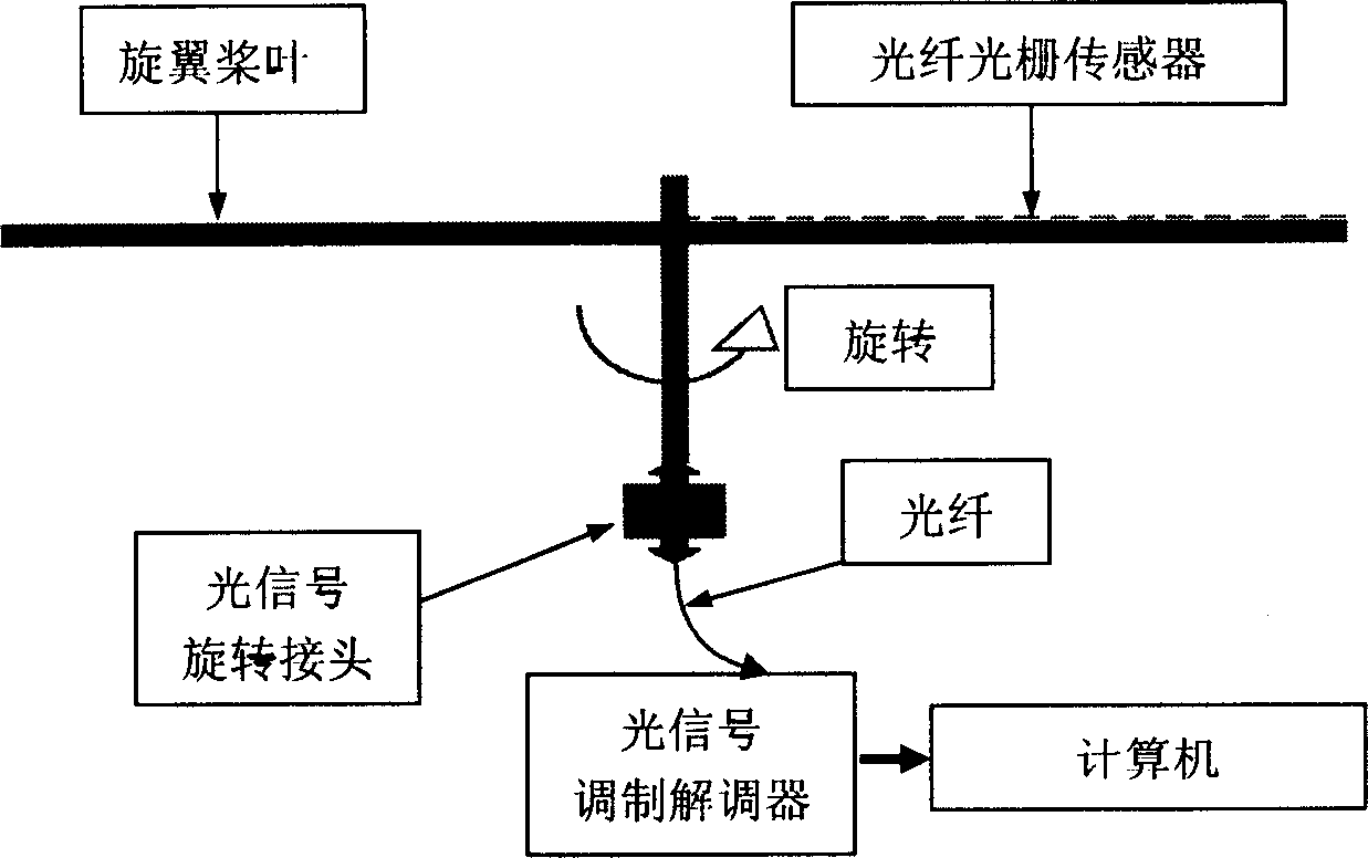
[0011] figure 1 It is a compositional block diagram of the rotor distributed load fiber grating sensing and measuring system of the present invention. It includes a Fiber Bragg Grating sensor pasted on the measuring surface of the rotor blade, an optical signal rotary joint, an optical signal modem, and a computer. The specific work process and implementation steps are as follows:

[0012] (1) Paste a string of Fiber Bragg Grating sensors at the measurement position on the upper surface of the blade;

[0013] (2) Connect the optical fiber on the paddle to the optical signal rotary joint, then lead the optical fiber out from the optical signal rotary joint, and connect it to the optical signal modem to transmit, receive and collect the optical signal. The optical signal modem is connected with the computer, and the collected signal is recorded and analyzed by the computer;

[0014] (3) Convert the dynamic optical signal collected at each measurement point under a certain tes...


PUM


Abstract

dThe invention discloses a rotor load distribution optical fiber grating sensing measurer, belonging to the wing load measure technique of gyropter. Said system comprises a optical fiber grating sensor adhered on the measure surface of rotor blade, whose optical fiber signal via the optical signal rotary connector connected on the blade is connected to the optical signal modulator/demodulator to be reflected, received and collected; the computer connected to the optical signal modulator/demodulator records and analyzes collected optical signal. The invention has simple process, high safety and detecting accuracy, which can be used in the dynamic strain measure of rotary structure, as the rotor load distribution.

Description

1. Technical field [0001] The invention relates to a rotor distributed load optical fiber grating sensing and measuring system, which belongs to rotorcraft rotor load measurement technology. 2. Background technology [0002] The rotorcraft hovers or flies in the air by the aerodynamic force generated by the rotation of the rotor, and determining the aerodynamic load on the rotor is crucial to the design of the rotorcraft. Due to the extremely complex aerodynamic flow field when the rotor rotates, the theoretical calculation error is very large, so it is necessary to use experiments to verify the accuracy of the theoretical calculation. In addition, after the development of the rotorcraft, ground tests and flight tests are carried out to measure the load on the rotor. Therefore, rotor load measurement is very important. [0003] At present, there are mainly two methods for rotor load measurement. One is to use a balance to measure the hexagon of the hub, but it cannot measu...

Claims


Application Information

Patent Timeline
IPC IPC(8): G01M9/00G01D5/353G01L1/24
Inventor 夏品奇陈文
Owner NANJING UNIV OF AERONAUTICS & ASTRONAUTICS
Why Eureka
Try Eureka