Magnetic valve bladder cycler drainage system and use method with urinary catheters

A technology of circulator, bladder, applied in the field of urinary catheter

Inactive Publication Date: 2006-10-11
THE HOOK RES FOUND
View PDF4 Cites 5 Cited by
  • Summary
  • Abstract
  • Description
  • Claims
  • Application Information

AI Technical Summary

Problems solved by technology

[0014] None of the devices and techniques of the above proposed patents add

Method used


Image

  • Magnetic valve bladder cycler drainage system and use method with urinary catheters
  • Magnetic valve bladder cycler drainage system and use method with urinary catheters
  • Magnetic valve bladder cycler drainage system and use method with urinary catheters

Examples


Embodiment Construction

[0045] Before explaining the disclosed embodiments of the present invention in detail, it is to be understood that the invention is not limited to the details of its application to the specific constructions shown, as the invention is capable of other embodiments. Also, the terms used herein are for the purpose of description and have a non-limiting meaning.

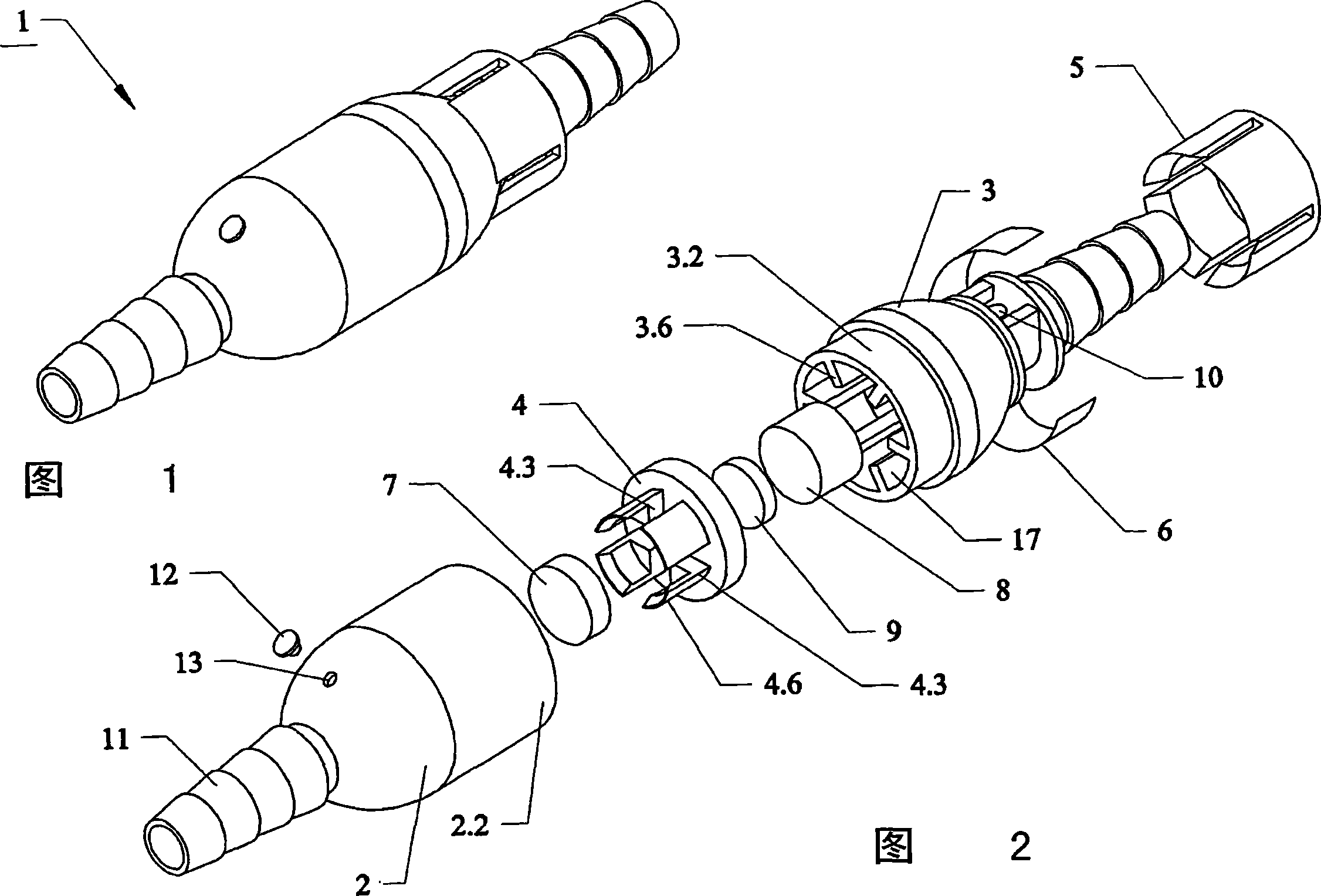
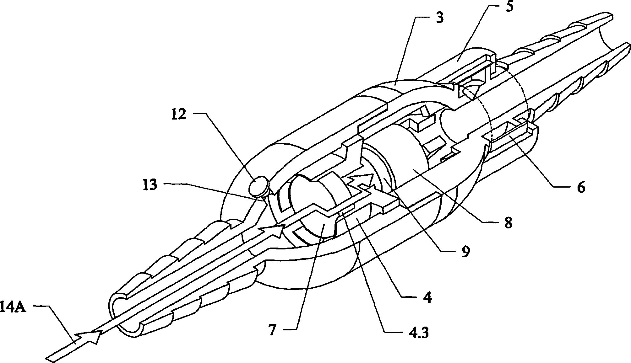
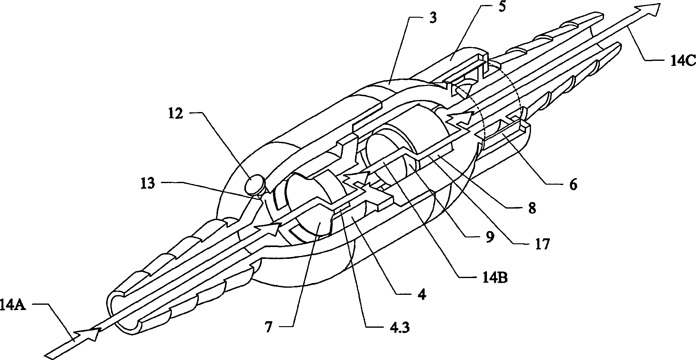
[0046] Figure 1 is a perspective view of the fully assembled passive magnetic valve for bladder circulation of the present invention 1 . FIG. 2 is an exploded view of the internal components of the invention 1 of FIG. 1 . Referring to Figures 1 and 2, this exploded view shows key components including the assembly. The inlet end or non-magnetic upper housing 2 has a female socket end 2.2 with a water-tight and air-tight connection that mates with a male sloping end 3.2 at the outlet end, or a non-magnetic lower housing 3. A moving magnetic valve member 8 is magnetically attracted in the direction of the valve port wall ...


PUM


Abstract

The invention relates to a low-pressure liquid flowing control magnetic valve (cycle device), relative system and method, which uses tube to discharge the liquid in bladder, wherein it can connect special discharge tube, to be one flow balance system; the cycle device can connect the catheter, to discharge bladder. Said valve is switched fully automatically, to discharge the urine, while it can respond the pressure of normal animal, or be operated by hand. The invention can be checked by U.S.F.D.A (America food and drug manage committee).

Description

[0001] Related applications [0002] This application claims priority to the following patent applications: US Provisional Patent Application 60 / 280,767, filed April 2, 2001, and US Provisional Patent Application 60 / 280,768, filed April 2, 2001, and filed September 25, 2001 US Provisional Patent Application 60 / 324,601. technical field [0003] This invention relates to urinary catheters, and more particularly to a method and apparatus for a pressure-actuated, magnetically controlled human (or animal) bladder voiding cycle valve system (urinary cycler) for restoring a catheter patient to circulation Normal human bladder function by way of irrigation and drainage. Background technique [0004] Urinary catheters bypass the normal bladder storage process and use only the detrusor muscle of the bladder to release urine. A catheter can be a necessary tool to open the bladder and can be used to urinate when a patient has difficulty urinating. Catheters can be life-saving tools b...

Claims


Application Information

Patent Timeline
IPC IPC(8): A61M5/178A61M5/32A61M5/00A61M27/00A61M1/00A61F5/44
CPCA61F5/4405
Inventor D·E·弗林奇鲍
Owner THE HOOK RES FOUND
Why Eureka
Try Eureka