Stacker

A palletizer and frame technology, applied in the field of object stacking, can solve the problems of unfavorable mechanized production, low efficiency, high labor intensity, etc., and achieve the effects of improving labor efficiency, best technical effect, and reducing labor intensity

Active Publication Date: 2006-10-18
FUJIAN HAIYUAN AUTOMATIC EQUIP CO LTD
View PDF2 Cites 23 Cited by
  • Summary
  • Abstract
  • Description
  • Claims
  • Application Information

AI Technical Summary

Problems solved by technology

[0002] Existing palletizing machines are as described in ZL99219349.4 and ZL01270171.8. The working process is to place the adobes and pallets extruded by the brick making machine on the wooden brackets, so in fact pallets are stacked instead of pallets. A piece of adobe, if you want to stack the individual adobes on the maintenance trolley, you need to manually stack them, which is labor-intensive and inefficient, which is not conducive to mechanized production

Method used


Image

  • Stacker
  • Stacker
  • Stacker

Examples


Embodiment Construction

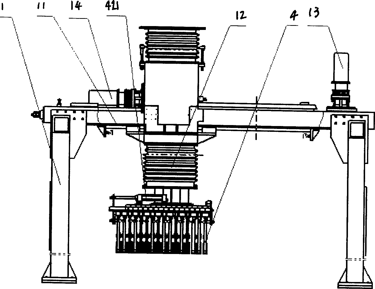
[0023] The present invention is described in detail below in conjunction with accompanying drawing

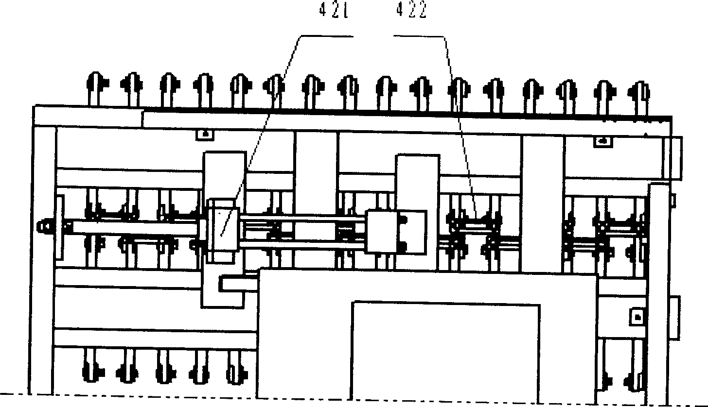
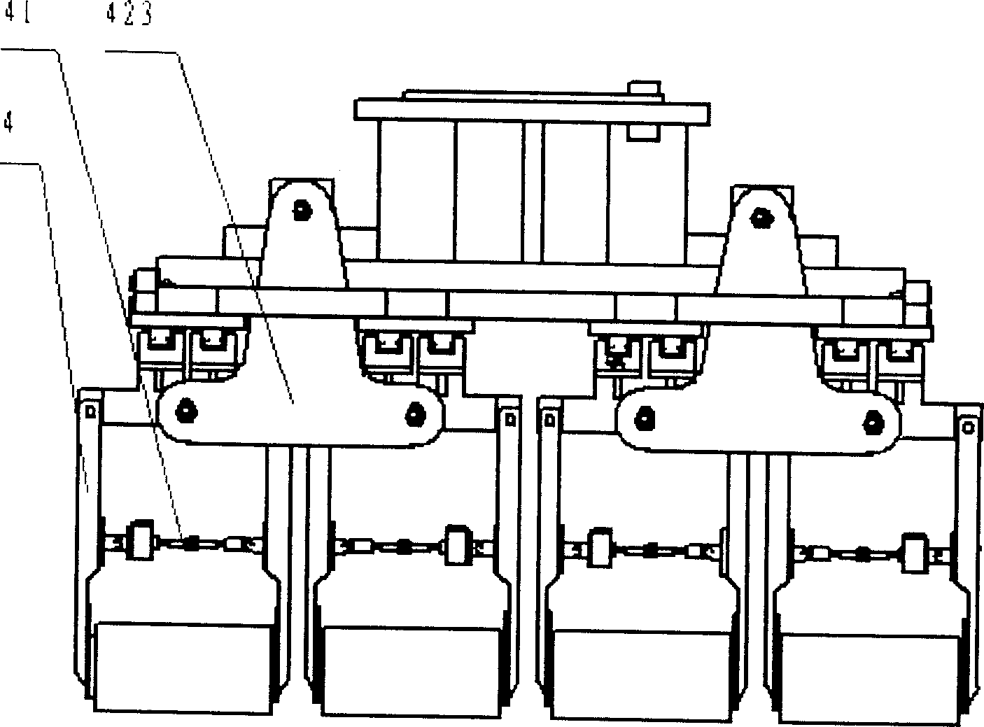
[0024] Such as figure 1 , figure 2 , image 3 Shown, a kind of palletizing machine comprises frame 1, control device, horizontal motor 13, vertical motor 14, is fixed with linear guide rail 11 on frame, is fixed with lifting base 12 on linear guide rail 11, and lifting base has two movements The direction is driven by two motors. A horizontal motor 13 is fixed on the frame 1 to control the lifting base 12 to move along the linear guide rail. A vertical motor 14 is fixed above the lifting base 12 to control the lifting base 12 to move up and down. The lifting base 12 There are 128 manipulators 4 installed at the bottom, each of which forms a pair, and there is a clamping mechanism 41 between each pair. The distribution rule is that there are four rows in the horizontal direction and 16 rows in the vertical direction. Every two rows of manipulators 4 are connected with a shrin...


PUM


Abstract

The present invention relates to stacking apparatus, such as brick, etc. and is especially one stacker comprising frame, controller and driving mechanism. Structurally, the stacker has one elevating pedestal on the straight line tracks and with two moving directions, one horizontal motor fixed on the frame for the horizontal motion of the elevating pedestal, one vertical motor fixed over the elevating pedestal for the vertical motion of the elevating pedestal, and several pairs of manipulators with clamping mechanism installed below the elevating pedestal. The stacker is used in stacking adobes in high efficiency.

Description

technical field [0001] The invention belongs to the stacking of objects, in particular to a stacking device for cubic objects such as bricks. Background technique [0002] Existing palletizing machines are as described in ZL99219349.4 and ZL01270171.8. The working process is to place the adobes and pallets extruded by the brick making machine on the wooden brackets, so in fact pallets are stacked instead of pallets. If you want to stack individual bricks on the maintenance trolley for bricks one by one, you need to manually stack them. The labor intensity is high and the efficiency is low, which is not conducive to mechanized production. Contents of the invention [0003] The purpose of the present invention is to overcome the disadvantages of the above-mentioned prior art, and provide a palletizer capable of directly palletizing adobes. [0004] The technical solution adopted in the present invention is a palletizer, including a frame, a control device, and power. A line...

Claims


Application Information

Patent Timeline
Patent Type & Authority Applications(China)
IPC IPC(8): B65G61/00B25J11/00
Inventor 李良光
Owner FUJIAN HAIYUAN AUTOMATIC EQUIP CO LTD
Why Eureka
Try Eureka