
Vanadium ion liquid flow accumulator battery
A liquid flow battery and vanadium ion technology, applied in secondary batteries, regenerative fuel cells, secondary battery manufacturing, etc., can solve the problems of volume limitation, battery failure, falling off, etc., and achieve the effect of high rate discharge cycle life
- Summary
- Abstract
- Description
- Claims
- Application Information
AI Technical Summary
Problems solved by technology
Method used
Image

Examples
Embodiment Construction
[0026] specific implementation
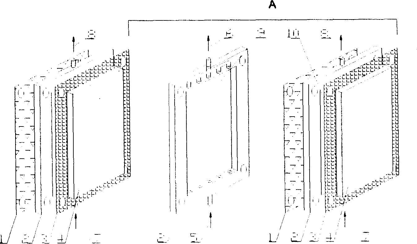
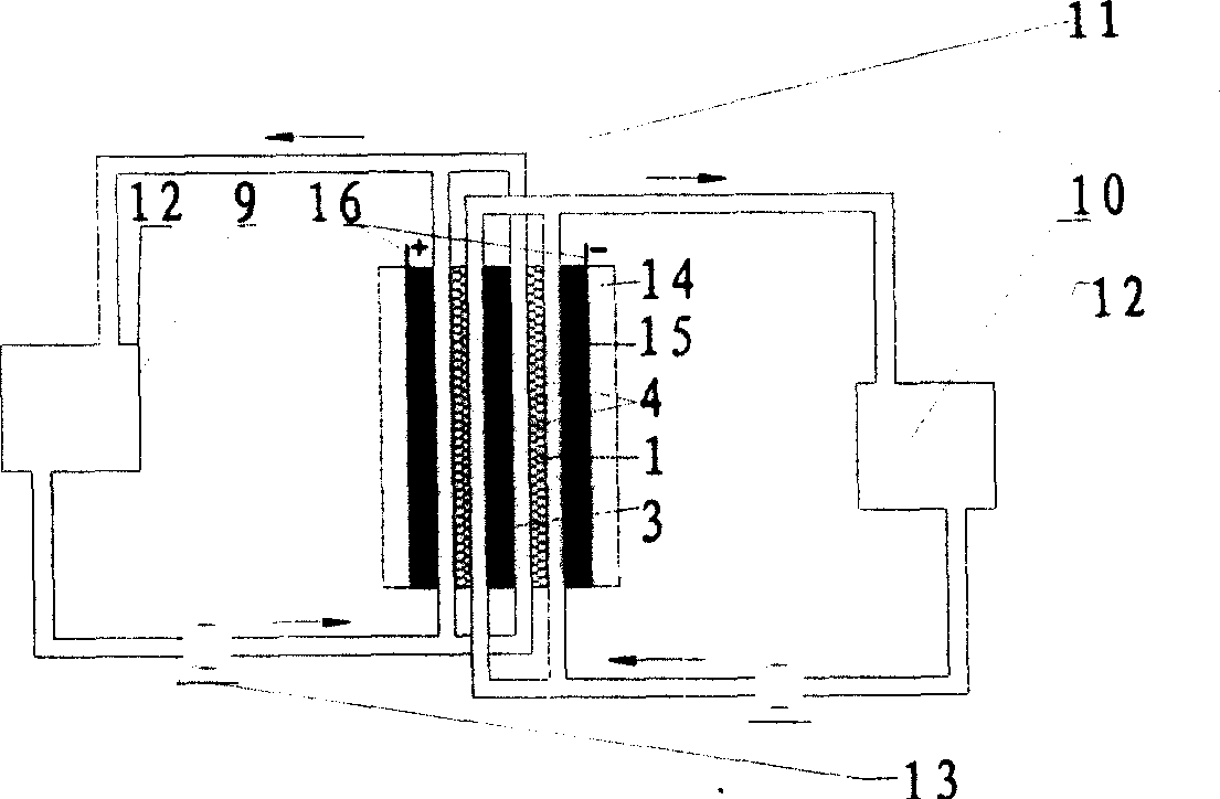
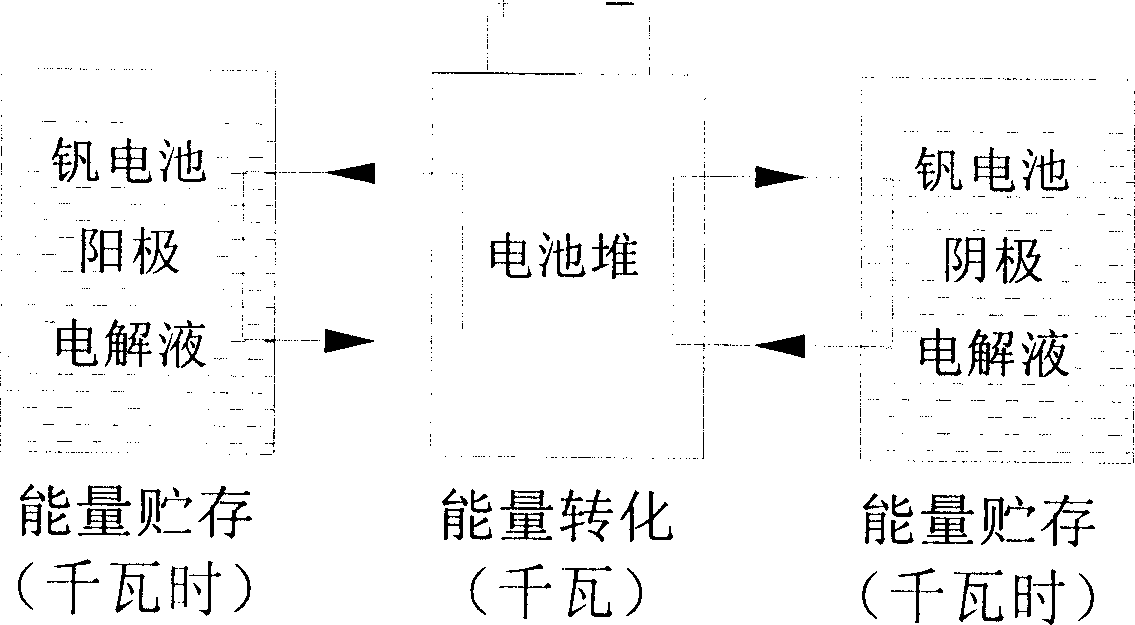
[0027] Two electrolyte pools 12 and several layers of battery cells are formed. The electrolyte pools 12 hold anode and catholyte solutions 9 and 10 respectively, and the anolyte solution 9 contains 9mol / L of H 2 SO 4 and 1~2mol / L (VO 2 ) 2 SO 4 Solution (optimally 2mol / L), the balance is water; catholyte 10 contains 9mol / L of H 2 SO 4 And 1~2mol / L VSO 4 Solution (optimally 2mol / L), the balance is water. The several layers of battery cells are stacked together, and each battery cell is formed by stacking bipolar electrodes 3, felt membranes 4, flow frames 2, separators 1, flow frames 2, felt membranes 4, and bipolar electrodes 3 in sequence , the diaphragm 1 separates the single cell into positive and negative two half-units; each electrolyte pool 12 is equipped with a pump 13, connected to each half-unit with a sealed pipeline 11; the flow frame 2 is a sealed pipeline 11 that flows through each half-unit The chann...
PUM
 Abstract
Description
Claims
Application Information