Eavcuation valve control device

A valve control and vacuum pumping technology, applied in the direction of fluid pressure control, non-electric variable control, control/regulation system, etc., can solve the problems of particle reduction and particle shedding

Active Publication Date: 2006-10-25
BEIJING NAURA MICROELECTRONICS EQUIP CO LTD
View PDF0 Cites 7 Cited by
  • Summary
  • Abstract
  • Description
  • Claims
  • Application Information

AI Technical Summary

Problems solved by technology

If the action of the valve is still performed according to the initially set time, then the valve with a high pumping speed (isolation valve 2) will be opened when the pressure is high, and the air flow

Method used


Image

  • Eavcuation valve control device
  • Eavcuation valve control device

Examples


Embodiment Construction

[0017] The following examples are used to illustrate the present invention, but are not intended to limit the scope of the present invention. Those of ordinary skill in the relevant technical field can also make various changes and modifications without departing from the spirit and scope of the present invention. Therefore All equivalent technical solutions also belong to the category of the present invention, and the scope of patent protection of the present invention should be defined by each claim.

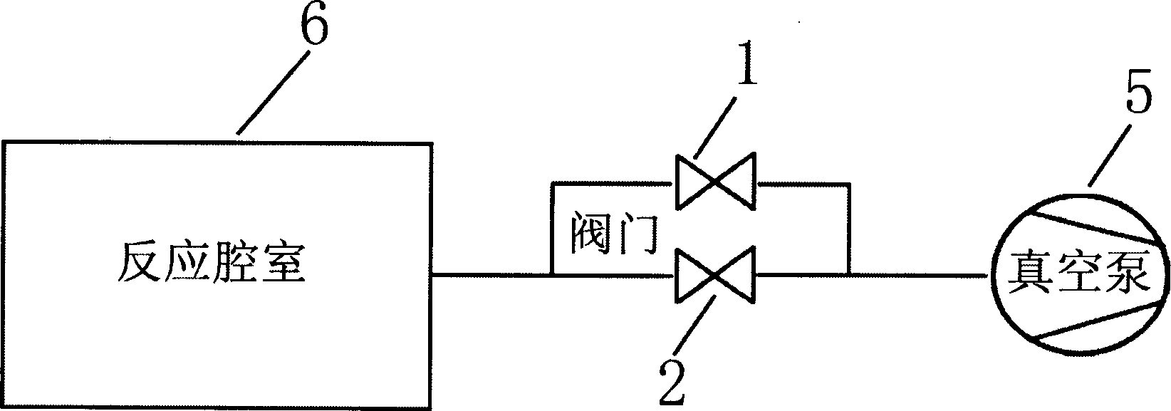
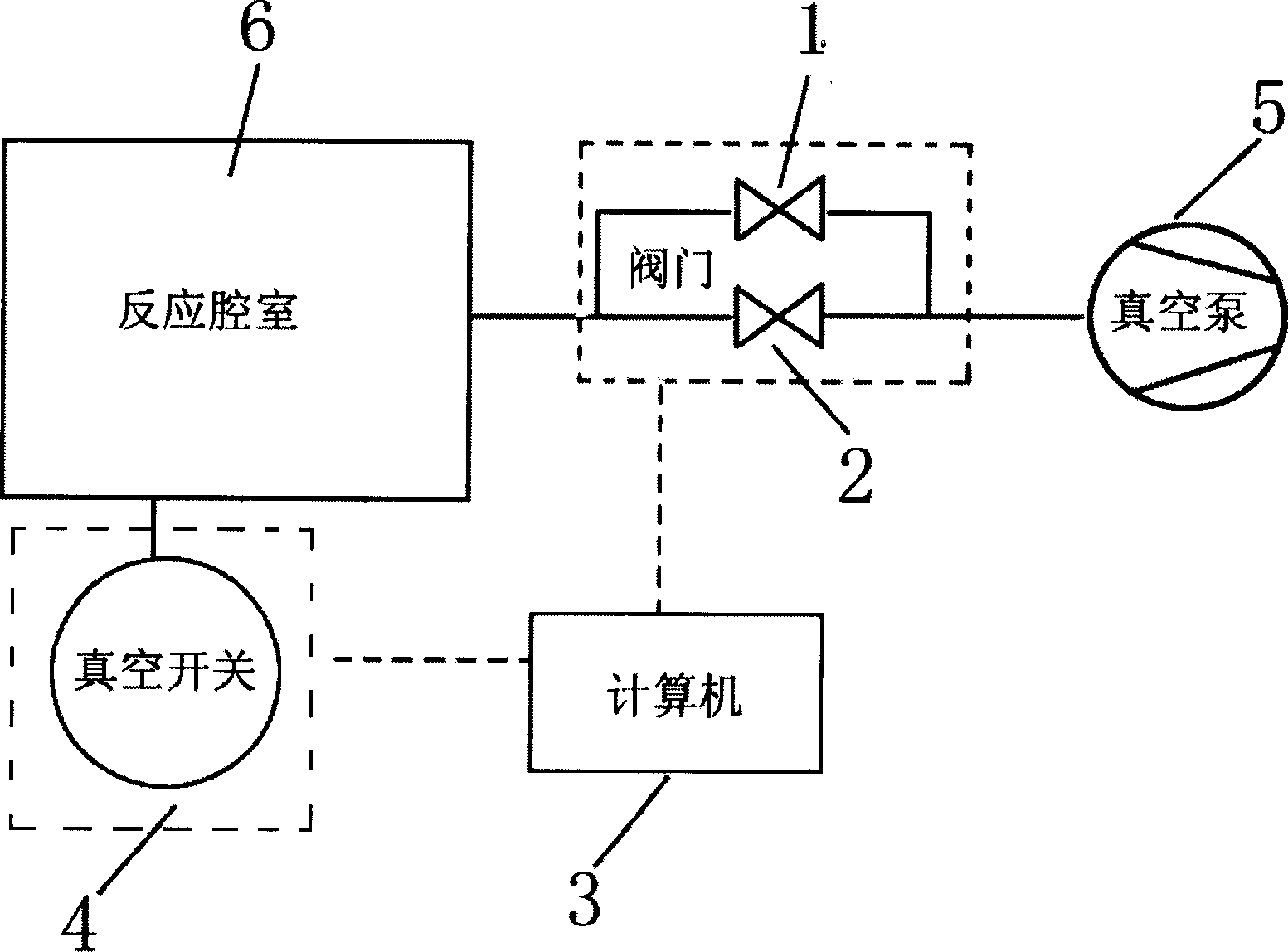
[0018] A vacuum valve control device, using 6LVV-DPFR4-C bypass valve 1, LPJ1-40 model isolation valve 2 and CPCI3700A industrial computer as valve control unit 3, bypass valve 2 and isolation valve 3 are connected in parallel to vacuum pump model 5 Between the chamber 6 and the vacuumed chamber, the valve control unit 3 controls the closing of the valves 1 and 2, and a vacuum switch 4 is also provided. The vacuum switch 4 detects the pressure of the vacuumed chamber 5 and comp...


PUM


Abstract

The present invention includes side valve, isolation valve, valve control unit, vacuum pump, cavity, and vacuum switch. Said invention can effectively control particulate pollution in reaction cavity vacuum-pumping process, even in unit platform state such as cavity state pumping speed varying.

Description

technical field [0001] The invention relates to a control device for a vacuum valve in semiconductor manufacturing, in particular to a control device for controlling the vacuum valve by using the pressure state of a chamber. Background technique [0002] The semiconductor manufacturing industry has extremely strict requirements on particle size. Every process must consider how to minimize the generation of particles, so as to improve the yield of production. When the etching machine is working, some by-products will be produced in the reaction chamber due to the bombardment and reaction of the plasma on the silicon wafer. Most of these by-products will be sucked away by the vacuum pump, and a small part will form polymers and adhere to the reaction chamber. interior wall. When evacuating the reaction chamber, if the pumping speed is high, turbulent flow will be generated in the reaction chamber, which will cause the polymer particles attached to the inner wall of the reacti...

Claims


Application Information

Patent Timeline
IPC IPC(8): G05D16/00G05D16/20
Inventor 杨崴
Owner BEIJING NAURA MICROELECTRONICS EQUIP CO LTD
Why Eureka
Try Eureka