Flue gas desulfurization control system of large coal-fired power plant

A control system, a technology for coal-fired power plants, applied in the separation of dispersed particles, chemical instruments and methods, separation methods, etc. Level of automation, saving time and money, effect of pollution prevention

Inactive Publication Date: 2008-04-02
SHANGHAI ELECTRICGROUP CORP
View PDF0 Cites 22 Cited by
  • Summary
  • Abstract
  • Description
  • Claims
  • Application Information

AI Technical Summary

Problems solved by technology

[0003] There are many flue gas desulfurization methods, among them, limestone wet flue gas desulfurization technology has been widely used, wet flue gas desulfurization technology is mature, high efficiency, low Ca / S ratio, reliable operation, but the treatment of desulfurization products is more troublesome, The process is complicated, and the floor area and initial investment are large
[0004] Due to the limitation of funds and production sites, most of the existing flue gas desulfurization technologies in my country only stay in the small test or pilot test stage. The focus of desulfurization control is on the control of the desulfurization process, and the focus on the state of desulfurization electromechanical equipment Monitoring and optimization often ignore the connection between systems, making it difficult to exert its due benefits
Therefore, it is difficult to be practically applied in large-scale thermal power plant flue gas desulfurization projects
[0005] In addition, the simulation platform of the flue gas desulfurization system of the power plant is still at the stage of pure software simulation, that is, the software simulation method is used to simulate the desulfurization system body, physical and chemical reaction process, data input / output and other processes. The fidelity of the simulation platform established in this way Not high, it is difficult to simulate complex working conditions and emergencies on site

Method used


Image

  • Flue gas desulfurization control system of large coal-fired power plant
  • Flue gas desulfurization control system of large coal-fired power plant

Examples


Embodiment Construction

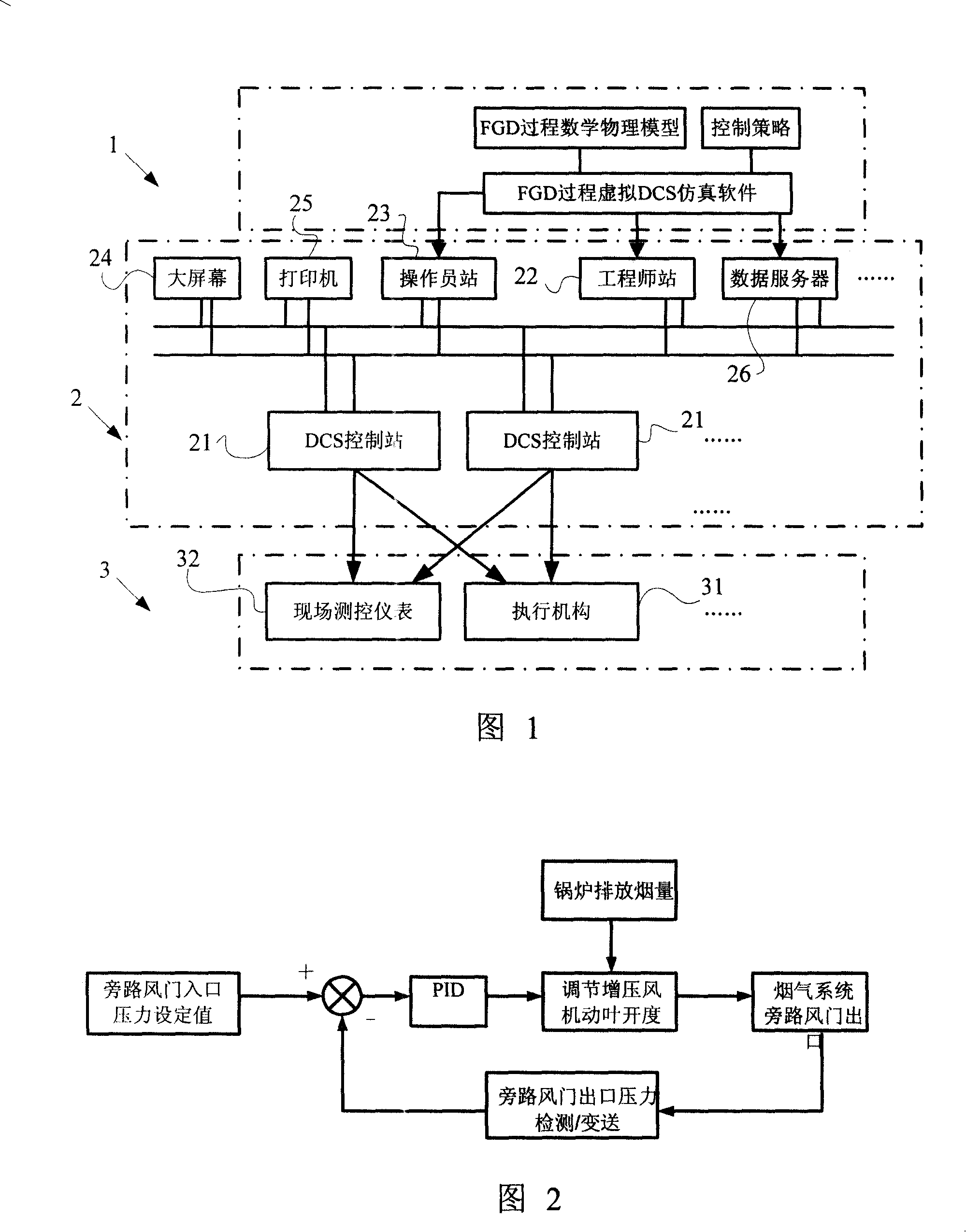
[0026] As shown in Figure 1, the flue gas desulfurization control system of a large-scale coal-fired power plant of the present invention includes a "virtual machine" part 1, a DCS control system 2 and a "real power" part 3 connected in sequence, wherein:

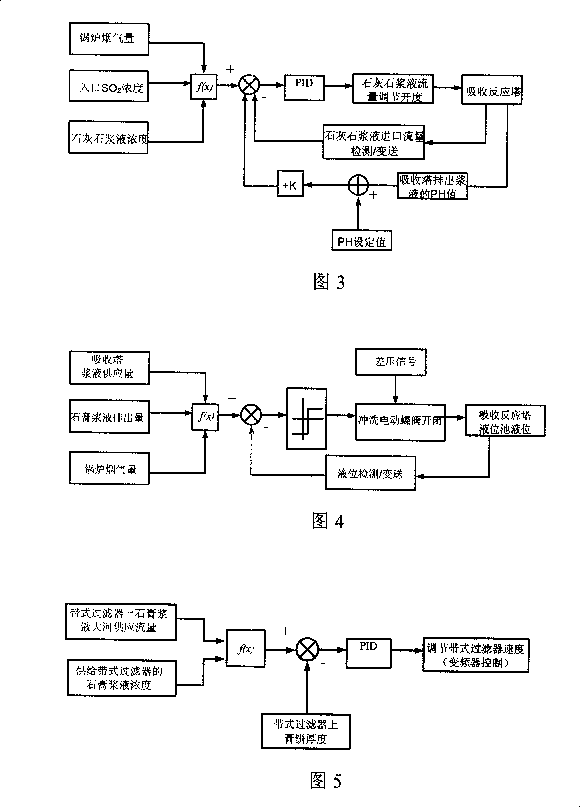
[0027] The "virtual machine" part 1 is the flue gas desulfurization simulation platform, including physical and mathematical models of several subsystems of flue gas desulfurization, several control loops, flue gas desulfurization start-stop sequence control system, alarm and thermal chain protection device. Several subsystems of flue gas desulfurization include: absorption tower unit, flue gas reheating unit, limestone slurry preparation unit and gypsum dehydration unit. Several control loops include: booster fan pressure control loop, limestone slurry flow control loop, absorption tower liquid level control loop and gypsum dehydration control loop.

[0028] The DCS control system 2 includes each control point 21 that is s...


PUM


Abstract

The invention provides a flue gas desulfuration control system for large coal-fired power plant and comprises an imaginary machine part which is a flue gas desulfuration simulation platform, a DCS control system which comprises control points arranged at in-site in a scattered way as well as working stations, monitors, printers, data servers and dual redundant optical fiber circular communication networks used for interconnection of the components; a real electricity part which is a real electricity part for flue gas desulfurization simulation platform and comprises an in-site input signal collection system, an in-site measurement and control instrument and an executing mechanism for simulation platform output signal. In addition, the real electricity part collects simulation signal and state of device coherent with in-site signal and sends into the flue gas desulfuration simulation platform through the DCS control system for performance check and control operation, and then outputted signal gets into the executing mechanism through the DCS control system and control of real device is realized. The invention is good for research and development of process, new technology and electrically controlled device of large desulfuration device, and then effectively controls carbon dioxide pollution of atmosphere and protects environment.

Description

technical field [0001] The invention relates to a research and development platform for a control system of a flue gas desulfurization process in a large coal-fired power plant, in particular to a control system for a flue gas desulfurization device in a power plant. Background technique [0002] In order to protect the environment and prevent the pollution of sulfur dioxide to the atmosphere, it is generally necessary to use flue gas desulfurization technology to control the emission of SO from coal-fired power plants. 2 emissions. [0003] There are many flue gas desulfurization methods, among them, limestone wet flue gas desulfurization technology has been widely used, wet flue gas desulfurization technology is mature, high efficiency, low Ca / S ratio, reliable operation, but the treatment of desulfurization products is more troublesome, The process is complicated, and the floor area and initial investment are large. [0004] Due to the limitation of funds and production...

Claims


Application Information

Patent Timeline
Patent Type & Authority Applications(China)
IPC IPC(8): B01D53/50B01D53/74
Inventor 陈建汤雪华陈江洪祁峰叶一枝王庆东
Owner SHANGHAI ELECTRICGROUP CORP
Why Eureka
Try Eureka