Transverse flow fan of indoor unit of air conditioner

A technology for air-conditioning indoor units and cross-flow fans, which is applied to mechanical equipment, radial flow pumps, machines/engines, etc., to achieve the effects of improving air supply performance, increasing strength, and avoiding uneven airflow

Inactive Publication Date: 2006-11-01
HAIER GRP CORP +1
View PDF4 Cites 10 Cited by
  • Summary
  • Abstract
  • Description
  • Claims
  • Application Information

AI Technical Summary

Problems solved by technology

[0008] (2) The action of the blade wake produces another kind of rotating noise
But in the ...

Method used


Image

  • Transverse flow fan of indoor unit of air conditioner
  • Transverse flow fan of indoor unit of air conditioner
  • Transverse flow fan of indoor unit of air conditioner

Examples


Embodiment Construction

[0044] Hereinafter, the present invention will be described in detail with reference to the drawings and embodiments.

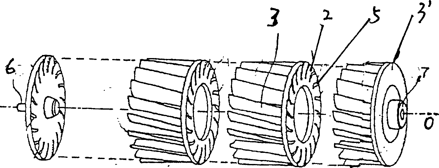
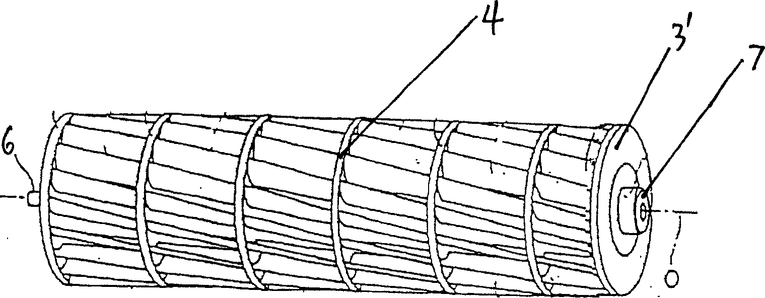
[0045] See first figure 1 , figure 1 It is a three-dimensional view of a multi-impeller. A plurality of blades 1 are obliquely fixed on a circular plate 2 at a predetermined angle α in the circumferential direction. In order to adapt to different arcs of different evaporators, in the present invention, the above-mentioned inclination angle α is set between 10°-25°. The above-mentioned inclination angle α refers to the acute angle formed between the line between the two end points of the blade cross section and the line between one end point and the fan shaft.

[0046] In addition, the above-mentioned blades 1 are inclined at a certain angle β relative to the central axis O of the circular plate in the longitudinal direction, and the installation intervals of the above-mentioned blades 1 are unequal intervals, and the included angle θ between the two adjacent bl...


PUM


Abstract

The invention relates to a transverse-flow fan for the wall room unit of the air conditioner, in which a plurality of blades is fixed on a disk to make above-mentioned each blade incline a certain angle to the central shaft of the disk, and meanwhile the mounting space of the said blades presents an unequal one and the angle included between the two adjacent blades and the central shaft of the disk is distributed randomly between 9~11deg. to form a section of the impeller with several blades. Several sections of above-mentioned impellers are firm-jointed to a needed length and two ends are sealed to form the transverse-flow fan of the invention.

Description

Technical field [0001] The invention relates to a fan of an indoor unit of an air conditioner, in particular to a cross-flow fan used in the indoor unit of a wall-mounted air conditioner. Background technique [0002] The wall-mounted split air conditioner indoor unit uses a cross-flow fan. The impeller of this fan has forward-facing blades, the axial width of the blades can be made very wide, in the shape of a drum, and both ends are sealed. When the impeller rotates, gas is sucked in between the blades. Under the action of centrifugal force, the gas is thrown around the impeller, the volume is compressed, the density increases, and static pressure is generated. At the same time, the airflow speed is increased to generate dynamic pressure (that is, to increase the kinetic energy). The gas is sent out from the tuyere. In this case, the central part of the impeller forms a low-pressure space, and the air is continuously sucked in, forming a continuous circulation of air in and out...

Claims


Application Information

Patent Timeline
IPC IPC(8): F04D17/04F04D29/28
Inventor 付裕王勇梁晓东王召兴楚人震杨挺石化永
Owner HAIER GRP CORP
Why Eureka
Try Eureka