

LCD and its drive circuit
A liquid crystal display and drive circuit technology, applied in static indicators, instruments, etc., can solve the problems of circuit area expansion, large area, etc., and achieve the effect of reducing size
- Summary
- Abstract
- Description
- Claims
- Application Information
AI Technical Summary
Problems solved by technology
Method used
Image

Examples
no. 1 example
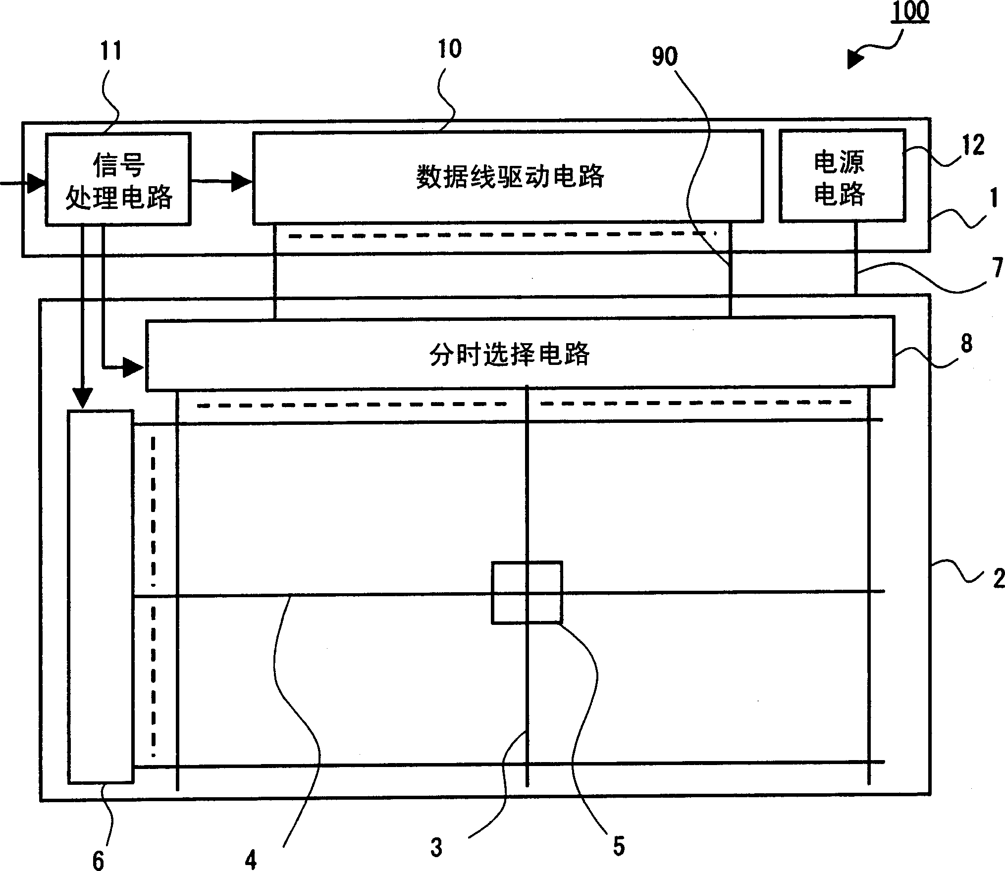
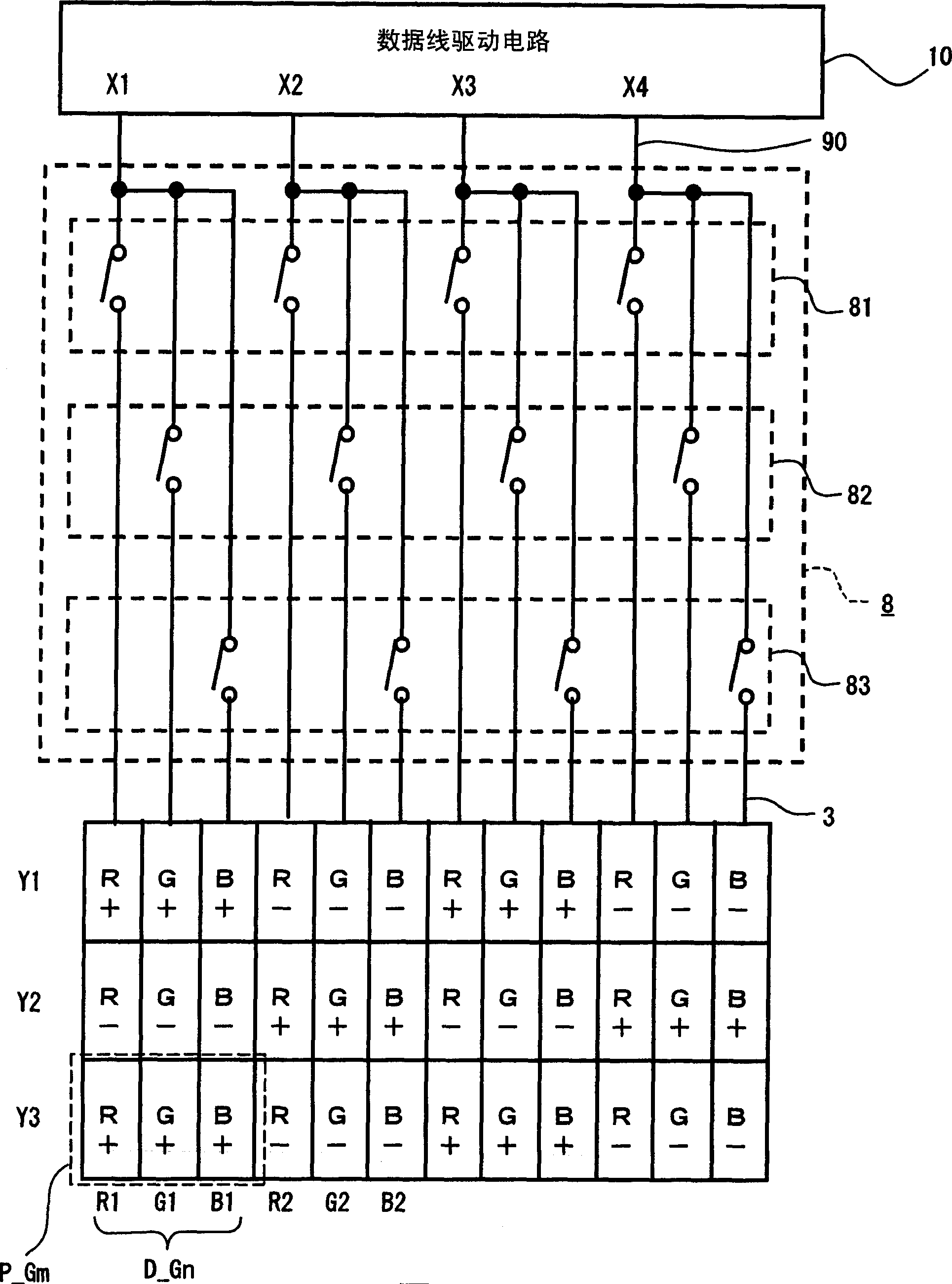
[0031] figure 1 is a block diagram of the liquid crystal display 100 of this embodiment. The liquid crystal display 100 of this embodiment includes a plurality of scanning lines 4 , a plurality of data lines 3 , and a pixel 5 arranged at each intersection of the plurality of scanning lines 4 and the plurality of data lines 3 . The liquid crystal display 100 further includes a plurality of pixel groups composed of pixels 5 , and the pixels are arranged at each intersection of a plurality of adjacent data lines 3 and a plurality of scanning lines 4 . Using the time-division driving method of sequentially outputting signals, signals of the same polarity are output to all data lines included in each pixel group of a plurality of pixel groups, and signals of opposite polarity are output to a plurality of pixel groups adjacent to each other. The sex-inverted signal is output to the data lines included in the pixel group.
[0032] That is to say, if figure 1 As shown in , a plural...
no. 2 example
[0082] In the first embodiment, the polarity switching circuit 70 is formed on the driver IC 1, and the time division selection circuit 8 is formed on the panel. Also, a selection circuit having a polarity switching function as well as a time-division switching function can be formed on the panel. Figure 12 is a detailed diagram of the D / A conversion circuit portion and the precharge circuit portion of the driver IC 1 according to the present embodiment.
[0083] In the first embodiment, the polarity switching circuit 70 is provided between the precharge circuit 60 and the output terminal Xn. However, in this embodiment, the precharge circuit 60 is directly connected to the output terminal Xn. like Figure 13 As shown, the time-division selection circuit 8 is composed of two switches for each data line 3 . Each switch is connected to an odd-numbered output terminal and an even-numbered output terminal, and includes a polarity switching function. Therefore, the number of s...
no. 3 example
[0096] In the second embodiment, a selection circuit having a polarity switching function and a time-division switching function is formed on the panel. A charge recovery circuit may be formed on the panel.
[0097] Figure 15 is a block diagram of the liquid crystal display 200 of the present invention. A charge recovery circuit 9 is further formed on the liquid crystal panel substrate 2 . The charge recovery circuit 9 is controlled by the signal output from the signal processing circuit 11 . Refer below Figure 16 The charge recovery circuit 9 will be described in detail. In the charge recovery circuit 9, two charge recovery switches 91 and 92 are provided in parallel to the data lines 3, and the other ends of the charge recovery switches 91 and 92 are connected to the bus lines 95 or 96 next to each data line group. Bus lines 95 and 96 are connected to charge recovery capacitors 93 and 94, respectively. During the first precharge period of the horizontal period, the c...
PUM
 Abstract
Description
Claims
Application Information