Eureka AIR delivers breakthrough ideas for toughest innovation challenges, trusted by R&D personnel around the world.

Optical recording material and optical recording medium

An optical recording medium, optical recording technology, applied in the direction of optical recording medium, recording medium material, recording/reproducing by optical method, etc., can solve the problems of difficulty in ensuring recording characteristics, increase in error rate, increase in jitter, etc., and achieve excellent recording Effects of Features

Inactive Publication Date: 2006-11-01
TDK CORPARATION
View PDF6 Cites 0 Cited by
  • Summary
  • Abstract
  • Description
  • Claims
  • Application Information

AI Technical Summary

Problems solved by technology

[0017] However, the inventors of the present invention have studied in detail the existing optical recording media represented by the optical recording media described in the above-mentioned Japanese Patent Documents 1 to 6, and found that even if the optical recording medium satisfies such existing evaluation criteria, Even when high-speed recording is performed, it is difficult to ensure sufficient recording characteristics
That is, it was found that when a dye component satisfying the evaluation criteria described in Japanese Patent Documents 1 to 6 is used as a constituent material of the recording layer and recording at a higher speed, it is difficult to obtain the desired pit length, resulting in increased jitter, Tendency to increase the error rate

Method used


Image

  • Optical recording material and optical recording medium
  • Optical recording material and optical recording medium
  • Optical recording material and optical recording medium

Examples


Embodiment 1

[0141] First, a polycarbonate resin substrate having a diameter of 120 mm and a thickness of 0.6 mm having pregrooves (0.12 μm in depth, 0.30 μm in width, and 0.74 μm in groove pitch) on one side was prepared. On the other hand, a dye component composed of the same constituent materials as Sample No. 1 was added to 2,2,3,3-tetrafluoropropanol so that the content thereof was 1.0% by mass, and a coating for a recording layer was prepared. liquid. The obtained coating solution was coated on the surface of the polycarbonate resin substrate on which the pregroove was formed, and dried at 80° C. for 1 hour to form a recording layer (thickness: 150 nm). Next, an Ag reflective layer (100 nm in thickness) was formed on the recording layer by sputtering, and an ultraviolet curable resin SD-1700 (manufactured by Dainippon Ink Chemicals Co., Ltd., trade name ) and then irradiated with ultraviolet rays to form a transparent protective layer (thickness: 8 μm) made of acrylic resin. Furthe...

Embodiment 2~5

[0142] (Examples 2-5, Comparative Examples 1-4)

[0143] As the pigment component, except that the pigment component composed of the same constituent material as sample No. 1 is used instead of the pigment component composed of the same constituent material as sample No. 2 to 9, the others are the same as in Example 1, The optical recording media (optical recording discs) of Examples 2 to 5 and Comparative Examples 1 to 4 were obtained.

[0144] (Evaluation of recording and reproduction characteristics)

[0145]The optical recording media of Examples 1 to 5 and Comparative Examples 1 to 4 were irradiated with laser light having a wavelength of 650 nm using a disc evaluation device (trade name: DDU-1000) manufactured by Palstec Industries, Ltd., and recorded at a linear velocity of 28 m / sec. In addition, the lens hole diameter NA of the optical head included in the above device was 0.60. Note that recording was performed at such a recording power that an eye pattern in which ...


PUM

PropertyMeasurementUnit
diameteraaaaaaaaaa
thicknessaaaaaaaaaa
thicknessaaaaaaaaaa

Abstract

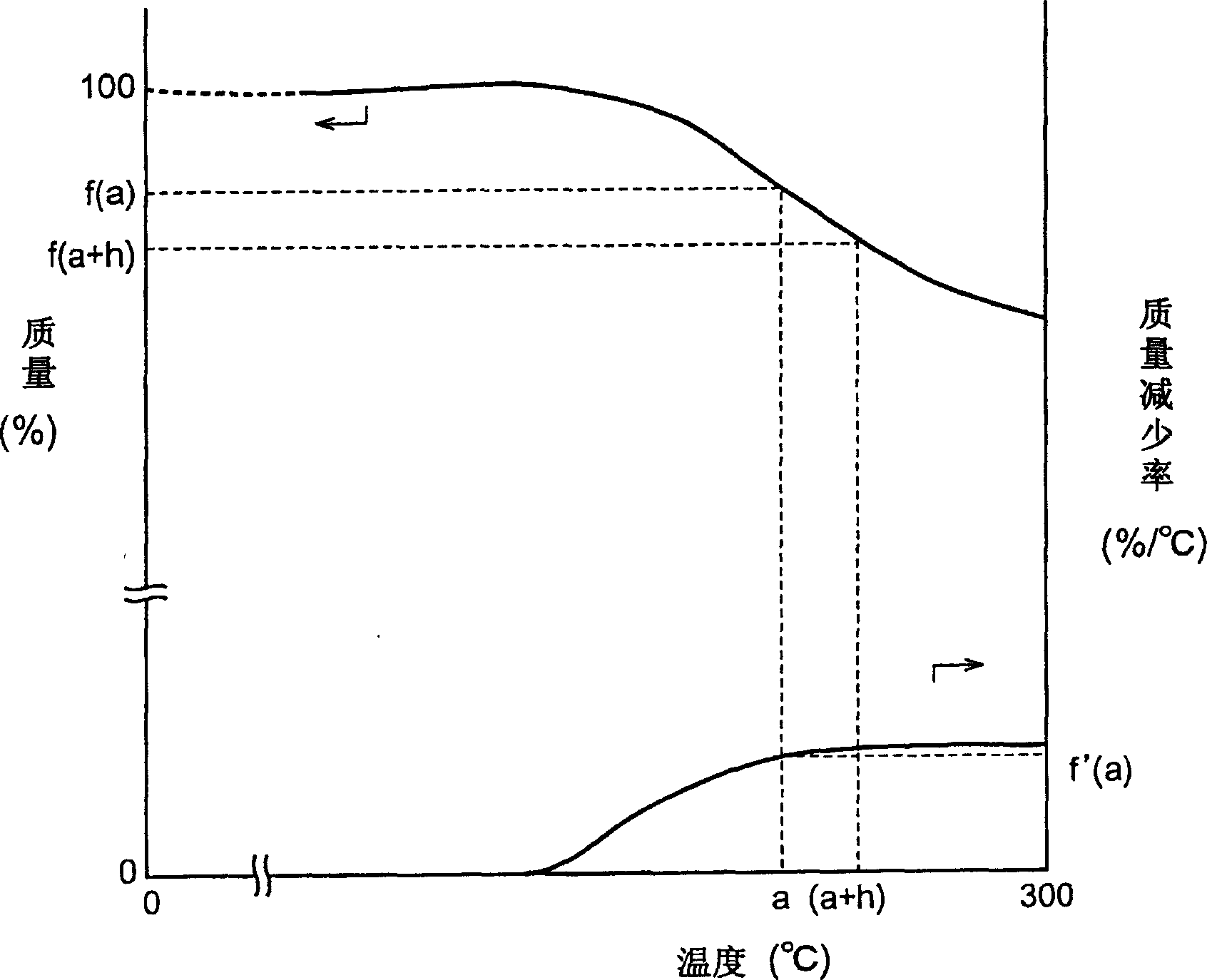
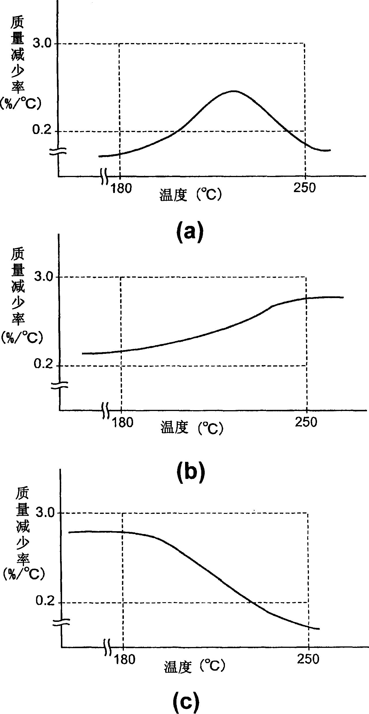
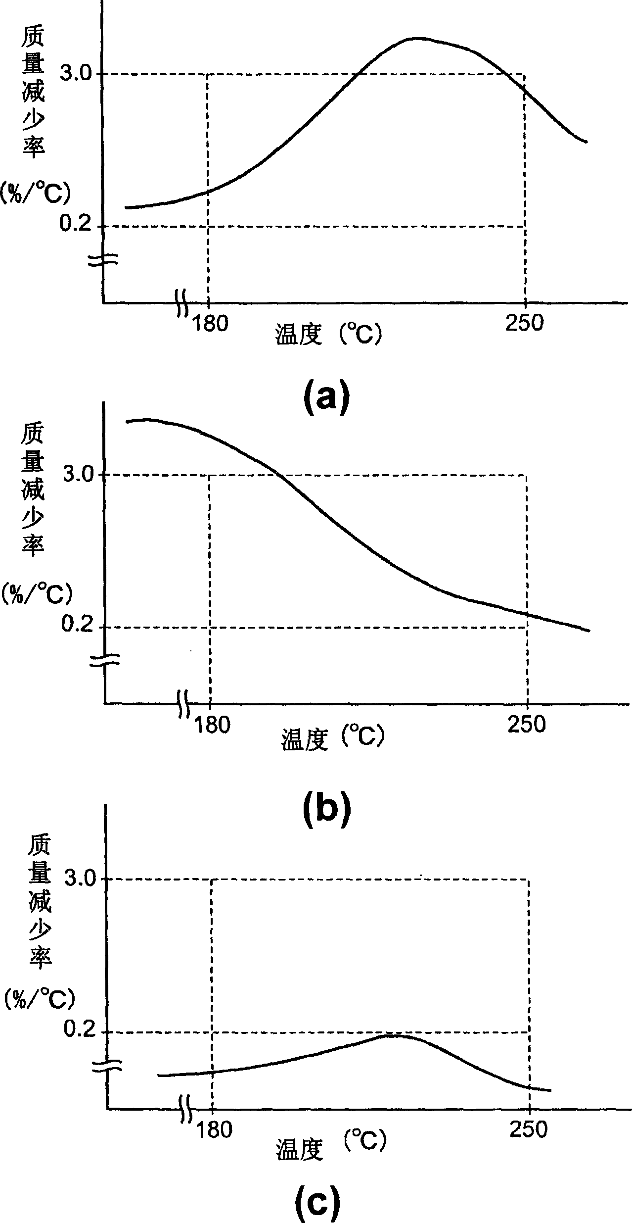
The optical recording material of the invention is an optical recording material used for an optical recording medium capable of recording information by irradiation of light, the optical recording medium being an optical recording medium which records information at a linear speed of at least 14 m / sec, wherein the dye component in the optical recording material comprises at least one type of chelate compound of an azo compound and a metal, and when the dye component is used as a sample for thermogravimetry in an inert gas atmosphere, the dye component sample exhibits a maximum weight reduction of 0.2-3.0% / DEG C. at 180-250 DEG C.

Description

technical field [0001] The present invention relates to an optical recording medium for recording information by light irradiation and an optical recording material used for the optical recording medium. Background technique [0002] In an optical recording medium, light such as a laser beam is generally irradiated to a recording layer, and information is recorded by utilizing shape change, magnetic domain change, phase change, etc. of the recording layer. Such optical recording media include, for example, write-once optical recording media having a recording layer containing an organic dye such as an azo dye, and are widely used as CD-R (compact disc-on-record) and DVD±R (DVD-on-record). [0003] The CD-R among the above-mentioned write-once optical recording media is usually composed of a recording layer mainly composed of a pigment, a reflective layer mainly composed of a metal, and an ultraviolet curable resin on a circular substrate having a guide groove. formed by the...

Claims


Application Information

Patent Timeline
Patent Type & Authority Applications(China)
IPC IPC(8): B41M5/26G11B7/24C09B45/04G11B7/244G11B7/246G11B7/247G11B7/249
CPCC09B23/06C09B29/0003C09B29/0014C09B29/0048C09B29/0085C09B29/0811C09B45/22G11B7/246G11B7/2463G11B7/2467G11B7/2472G11B7/2475G11B7/2478G11B7/249G11B7/2492G11B7/2498G11B7/2533G11B7/2534G11B7/2536G11B7/259G11B2007/24612
Inventor 门田敦志新海正博田辺顺志
Owner TDK CORPARATION
Why Eureka
Eureka Blog
Learn More