
Portable electronic device and its radiating method and charging seat

A technology of electronic devices and heat dissipation methods, which is applied in the direction of coupling devices, components of connecting devices, circuits, etc., can solve problems such as endangering user safety, increasing danger, and lithium battery explosion, so as to improve service life and avoid battery explosion , the effect of reducing the internal temperature

Inactive Publication Date: 2006-11-01
HTC CORP
View PDF0 Cites 5 Cited by
  • Summary
  • Abstract
  • Description
  • Claims
  • Application Information

AI Technical Summary

Problems solved by technology

However, too high temperature is easy to damage electronic components and light-emitting components, reducing their service life
Moreover, since the currently used batteries are lithium batteries, excessive temperature may cause the lithium battery to explode, endangering the safety of users.
In particular, if the portable electronic device is used to perform wireless Internet access or other power-consuming functions while charging the portable electronic device, the temperature inside the portable electronic device will increase significantly, increasing the danger of use.

Method used


Image

  • Portable electronic device and its radiating method and charging seat
  • Portable electronic device and its radiating method and charging seat
  • Portable electronic device and its radiating method and charging seat

Examples


no. 1 example

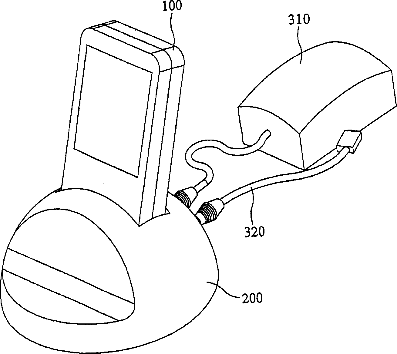
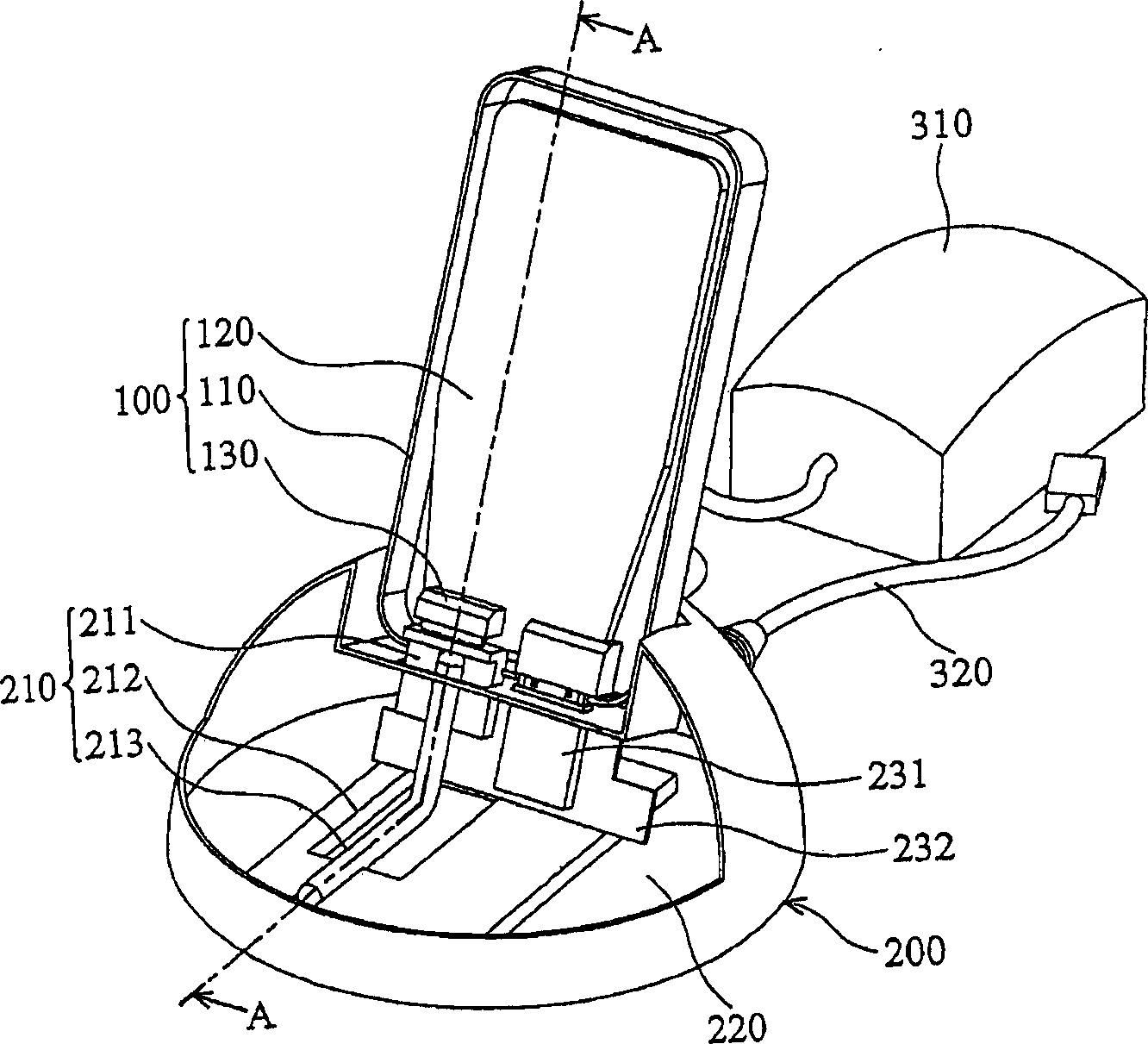
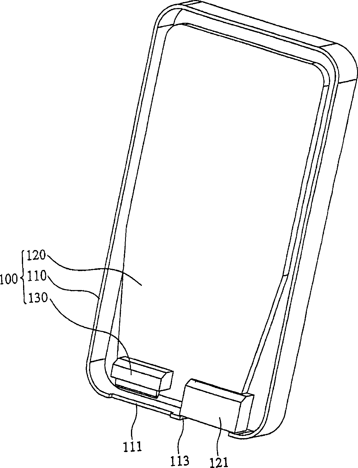
[0020] Referring to FIG. 2a, which shows the internal structure of the portable electronic device 100 and the charging dock 200 according to the first embodiment of the present invention, the structures of the portable electronic device 100 and the charging dock 200 are respectively described below. Refer to Figure 2b , The portable electronic device 100 includes a housing 110, a first circuit board 120, and a heat conduction module 130. The housing 110 includes a first opening 111 and a third opening 113. The first circuit board 120 and the heat conduction module 130 are both disposed in the housing 110. The heat conduction module 130 is disposed on a circuit clearance area on the first circuit board 120 and corresponds to the first opening 111. The first circuit board 120 includes a universal serial bus (USB) connection port 121 corresponding to the third opening 113.

[0021] Refer to Figure 2c The charging base 200 includes a heat dissipation module 210, a cavity 220, a seco...

no. 2 example

[0029] Refer to Figure 5a , Which shows the second embodiment of the present invention. The main difference from the first embodiment lies in the heat conduction module 130' and the connection relationship between the heat conduction module 130' and the heat conduction element. Refer to Figure 5b , Which shows the detailed structure of the thermal conduction module 130' and its adjacent components. Compared with the first embodiment, the first circuit board 120 in the second embodiment is closer to the back side of the portable electronic device. The heat conduction module 130' includes a metal sheet 133' and a housing 134'. The metal sheet 133' is partially located in the housing 134'. The metal sheet 133' is made of copper and includes a first part 131' and a second part 132'. The second part 132' is an elastic structure, and when not in contact with the heat conducting element, the second part 132' is in a first position. The first part 131' contacts the first circuit board 1...


PUM


Abstract

The invention in concerned with a radiation method, which processes radiate to a portable electronic equipment, including: provides a heat conducting module and a radiation module, the heat conducting module is set in the portable electronic equipment, the radiation module is set in a charging seat, the radiation method contact the heat conducting module, educes the heating quantity of the portable electronic equipment by the conductive mode, finally the radiation method processes the radiation of the heating quantity by the mode of the convection or the conduction.

Description

Technical field [0001] The invention relates to a portable electronic device and a heat dissipation method thereof, in particular to a heat dissipation method using a charging base to dissipate heat. Background technique [0002] During the charging process of a portable electronic device (for example, a personal digital assistant PDA or a mobile phone), the high heat generated by the charging chip will be transferred through the printed circuit board to other electronic components and light-emitting components inside the portable electronic device And battery and other parts, and raise the temperature of each part. However, excessively high temperatures can easily damage electronic components and light-emitting components, reducing their service life. Moreover, since the batteries currently used are lithium batteries, excessively high temperatures may cause the lithium batteries to explode, endangering the safety of users. In particular, if the portable electronic device is used...

Claims


Application Information

Patent Timeline
Patent Type & Authority Applications(China)
IPC IPC(8): H05K7/20G12B15/06H01R13/46H01R13/533H05K1/02
Inventor 黄怡彰林耀宗
Owner HTC CORP
Learn More