Machine for grinding optical workpieces, in particular plastic eyeglass lenses

一种光学工件、机加工的技术,应用在光学元件、光学元件、金属加工机械零件等方向,能够解决大成本等问题,达到短机加工时间、高形状精度的效果

Active Publication Date: 2006-11-08
SATISLOH AG
View PDF5 Cites 8 Cited by
  • Summary
  • Abstract
  • Description
  • Claims
  • Application Information

AI Technical Summary

Problems solved by technology

[0007] However, known mechanisms are entirely manually adjusted
In order to be able to carry out automatic adjustment even during operation of the machining machine tool, an associated CNC (Computerized Numerical Control) controlled adjustment spindle must be provided, which entails considerable costs

Method used


Image

  • Machine for grinding optical workpieces, in particular plastic eyeglass lenses
  • Machine for grinding optical workpieces, in particular plastic eyeglass lenses
  • Machine for grinding optical workpieces, in particular plastic eyeglass lenses

Examples


Embodiment Construction

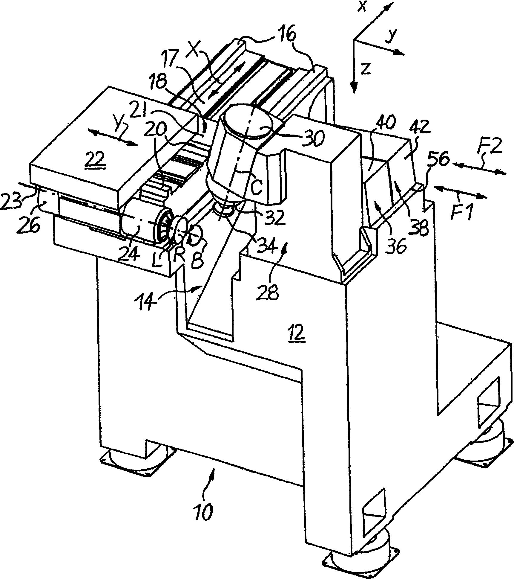
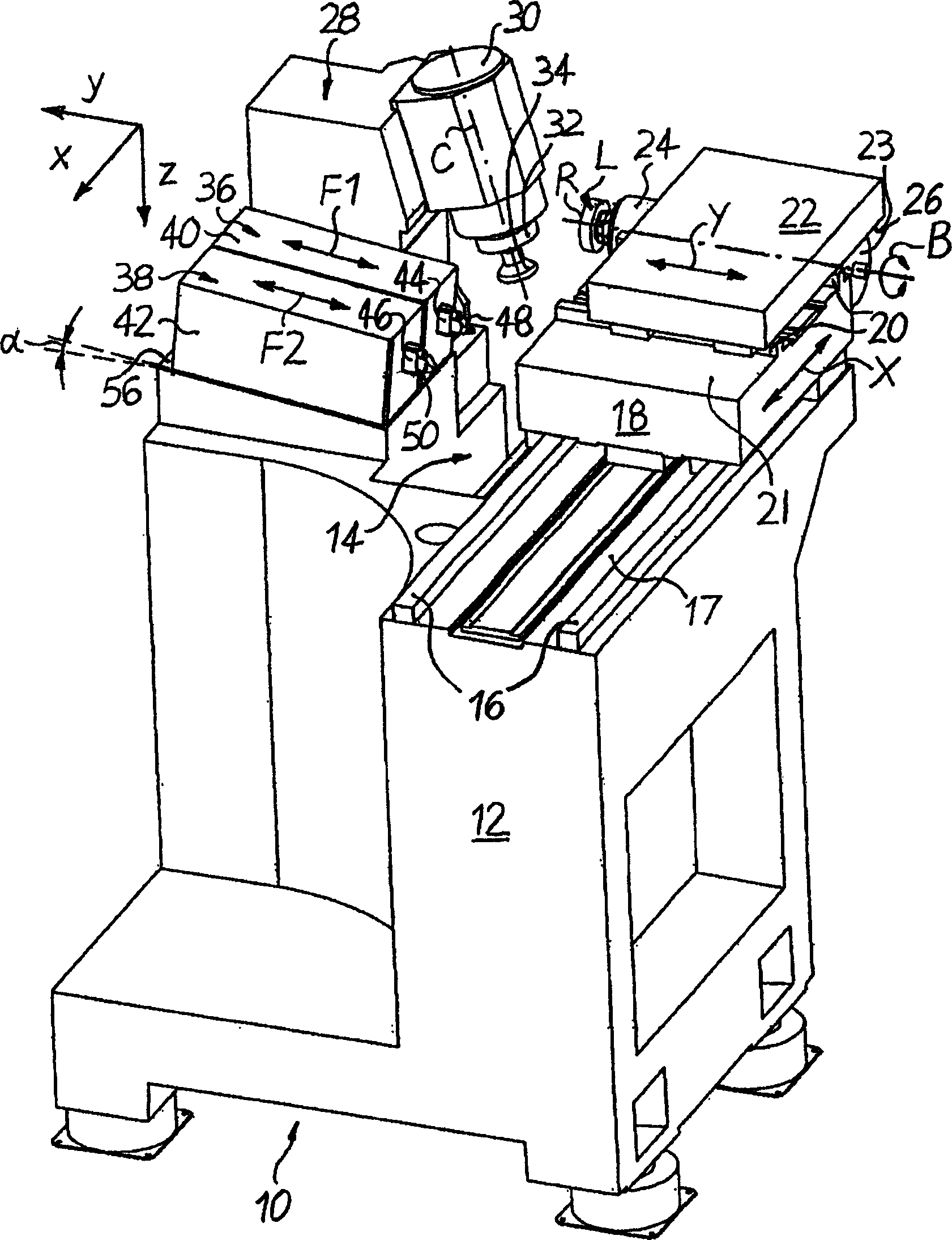
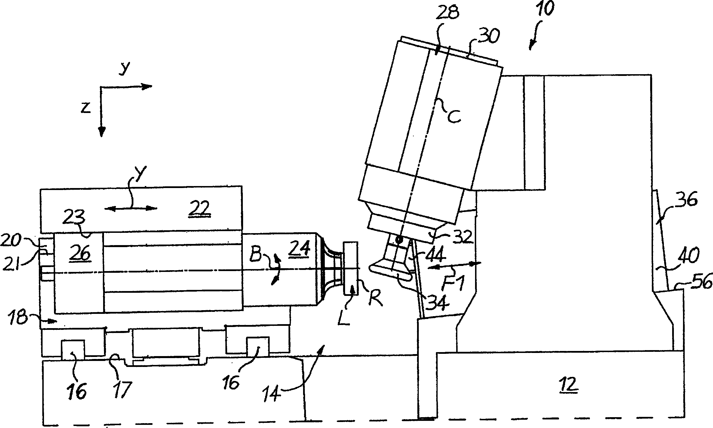
[0023] Figures 1 to 5 A CNC-controlled machine tool 10, in particular for machining the surface of a plastic ophthalmic lens L, is schematically shown in a Cartesian coordinate system, where the lowercase letters x, y, and z represent the width direction of the machine 10 (x ), the length direction (y) and the height direction (z).

[0024] like Figures 1 to 5 As shown, machine tool 10 includes a frame 12 defining a machining area 14 . exist figure 1 fixed on the left-hand side of the machining area 14, in figure 1 On the upper mounting surface 17 of the frame 12 are two guide rails 16 extending parallel to each other in the (horizontal) width direction x. Mounted movably on rail 16 is an X slide adjustable in both directions of the X axis in a CNC controlled positioning manner by associated CNC drive and control elements (not shown).

[0025] exist figure 1 Two further guide rails 20 extending parallel to each other in the (likewise horizontal) length direction y and ...


PUM


Abstract

The unit (10) comprises a basic frame (12) with two crosswise moving carriages (18,22) one of them (22) fitted with the work-piece holding spindle (24). The machining device (28) is located opposite at the frame (12) connected to a fast tool arrangement (36,38) assembled of two parallel positioned and alternately moving shuttles. The fast tool unit (36,38) and the work-piece holding spindle (24) are positioned in an acute angle in order to compensate a possible height deviation of the cutting blades.

Description

technical field [0001] The invention relates to a machine tool according to the preamble of claim 1 for machining optical workpieces, in particular plastic spectacle lenses. Background technique [0002] When machining plastic ophthalmic lenses, it is common to use a lens "blank" formed by injection molding of plastic having a standard machined convex surface, for example with a spherical or progressive shape. Machining the internal or prescription surface (usually concave) to a spherical, aspheric, curved, non-curved, progressive, or random form, depending on the desired optical effect Geometry (progressive lens surface). When the inner surface is machined using typical conventional processes, the lens sheet blank is placed with its outer surface on a stand, cutting or turning machining is performed to produce an optically effective shape, followed by finish grinding or polishing, achieve the desired surface quality. [0003] For the above-mentioned turning process, high...

Claims


Application Information

Patent Timeline
Patent Type & Authority Applications(China)
IPC IPC(8): B23B5/36B23B5/40
CPCB24B13/046B24B13/06B24B41/00B24B47/20B24B47/22B23Q2230/004B23Q1/60Y10T82/2502Y10T82/10Y10T82/2541B29D11/00942
Inventor M·萨冯E·麦克帕森
Owner SATISLOH AG
Why Eureka
Try Eureka