Luneberg lens and antenna device using the same

A kind of lens and Bobo technology, applied in the direction of antennas, electrical components, etc., can solve the problems of irremovable, reduced electrical performance, weakened sealing function, etc., to achieve the effect of suppressing the decline of electrical performance, reducing the number of manufacturing processes, and excellent moisture resistance

Inactive Publication Date: 2006-11-15
SUMITOMO ELECTRIC IND LTD
View PDF0 Cites 3 Cited by
  • Summary
  • Abstract
  • Description
  • Claims
  • Application Information

AI Technical Summary

Problems solved by technology

In addition, the thin cover layer is easy to deform due to loads such as wind pressure, and when sealing reflectors, etc., it is easy to weaken the sealing function.
[0014] In addition, in the case where it has been used for many years, the deterioration due to ultraviolet rays, etc. is strengthened, especially in the case of a thin cover layer, there are cases where cracks are generated in the cover layer, and when objects blown by a storm are knocked Cracks and damages while on it, and rainwater etc. flow into the lens part from the cracks and damages generated, significantly degrading the electrical performance of the lens, which also becomes a problem
For Lumber lenses made of resin foam beads fused together, when rainwater enters the gaps between the beads on the surface or the gaps in the middle layer, the water cannot be removed for a long time and remains, resulting in a significant decrease in electrical performance situation for a long time
[0015] Meanwhile, in the case where the manufactured Lunberg lens is transported to another factory where an antenna is constructed, it is conceivable that the lens absorbs moisture during transportation and storage, and there is a possibility that the electrical characteristics of the antenna are lowered

Method used


Image

  • Luneberg lens and antenna device using the same
  • Luneberg lens and antenna device using the same
  • Luneberg lens and antenna device using the same

Examples


Embodiment 1

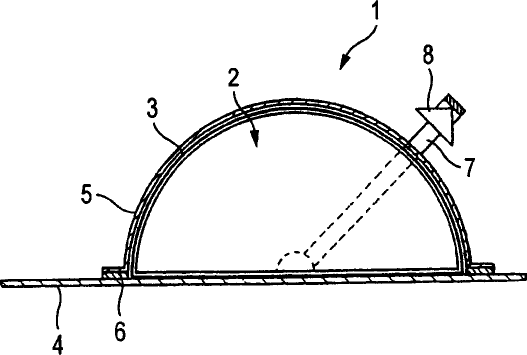
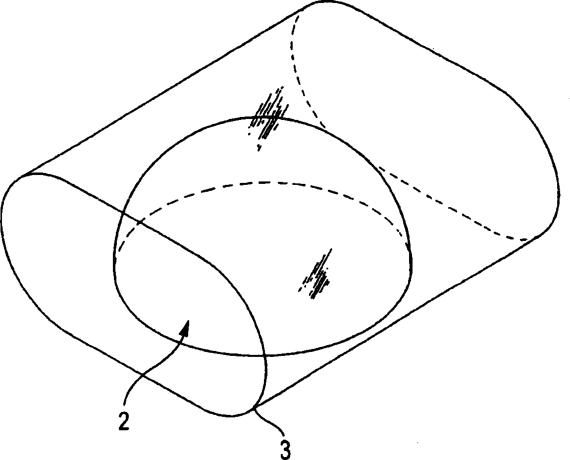
[0050] Such as image 3 As shown, a hemispherical lens 2 with a diameter of 45 cm is placed in a cylindrical PP shrink film 3 (magic wrap PP PA (30 μm thick) produced by Gunze Co., Ltd.), and the upper and lower sides of the shrink film 3 are fused to be in the The flat end surface of the lens (the surface in contact with the reflector) is drawn into a circle approximately 10 mm outside, and sealed ( Figure 4 The 9 in represents the sealing part), and cut off the excess edge. Next, a small hole for releasing the air inside the shrink film 3 is formed by a needle on the center portion of the flat end face side of the lens 2, thereafter, the entire area of ​​the film is heated by a dryer whose temperature is adjusted to approximately 100° C., and then , obtained a film-sealed Lunberg lens, the shrink film 3 of which fits closely on the surface of the lens 2 .

[0051] Next, this lens was subjected to a moisture resistance test after closing the holes for air release. The tes...

Embodiment 2

[0055] The film-sealed hemispherical Lunberg lens prepared in Example 1 was stored in a dark place (in a warehouse at a temperature of approximately 20° C.) for one month, after which it was placed on a reflective plate, and the gains before and after storage were measured and compared. As a result, the gain before and after storage was 33.5 dB, and the influence due to moisture absorption was not found.

Embodiment 3

[0059] A hemispherical lens 2 with a diameter of 45 cm was placed in a cylindrical EVA shrink film (SUNTEC S CF100 (10 μm thick, produced by Asahi Kasei Co., Ltd.)), and in the same manner as in Example 1, the upper and lower sides of the shrink film were sealed so that The position approximately 10 mm outside the bisected section of the spherical surface of the lens (the surface in contact with the reflector) is drawn into a circle, and the redundant edge is cut off. Next, a small hole for releasing the air inside to shrink the film 3 is formed by a needle on the center portion of the flat end face side of the lens 2, thereafter, the entire area of ​​the film is heated by a dryer whose temperature is adjusted to approximately 100° C., and Subsequently, Lunberg lenses of the film-sealed type were obtained, the shrink film of which closely fits the surface of the lens.

[0060] Then, the lens is placed on the reflector and covered with a cover that fits tightly on the outside t...


PUM


Abstract

A luneberg lens, which is configured by combining a plurality of lens parts, has a problem on keeping of a combined condition of lens parts and securement of good moisture prevention, and displacement of lens parts not only becomes a cause of cost-up but also has a bad influence on an electric performance, and furthermore, intrusion of moisture and humidity deteriorates an electric performance, and therefore, these problems are solved by a simple and inexpensive method. A lens portion 2, which is configured by combining lens parts of spherical core and spherical shell-like resin foams, is configured by a luneberg lens which is sealed by a synthetic resin film 3 which is formed along a surface of that lens portion 2 and in which a thickness is 100 m or less and of which own relative dielectric constant is higher than a relative dielectric constant of the outermost layer of the above-mentioned lens portion.

Description

technical field [0001] The present invention relates to a Lunberg lens for transmitting or receiving radio waves to and from broadcasting and communication satellites, etc., and an antenna device using the same. Background technique [0002] As a sphere formed by a dielectric material as the basic form and according to the relative permittivity εr of each part of the lens, it roughly obeys the formula εr=2-(r / R) 2 , assuming that the radius of the sphere is R and the distance from the center of the sphere is r, the Lunberg lens, a radio wave lens designed in such a way, is known as a multi-correspondence radio wave lens through which it is possible to communicate with multiple other talking parties simultaneously. [0003] Meanwhile, this Lunberg lens, which is the prior art, shows some problems in the following patent documents 1 to 3 and so on, but these documents have no introduction about the handling and moisture-proofing of the lens. [0004] Patent Document 1: Unexam...

Claims


Application Information

Patent Timeline
Patent Type & Authority Applications(China)
IPC IPC(8): H01Q15/08H01Q19/10
CPCH01Q15/08H01Q19/104
Inventor 黑田昌利木村功一
Owner SUMITOMO ELECTRIC IND LTD
Why Eureka
Try Eureka