Sheet material compression clamp
A technology of sheet materials and fixtures, which can be used in analysis materials, measuring devices, instruments, etc., and can solve problems such as difficulty in disassembling test pieces
- Summary
- Abstract
- Description
- Claims
- Application Information
AI Technical Summary
Problems solved by technology
Method used
Image
Examples
specific Embodiment approach 1
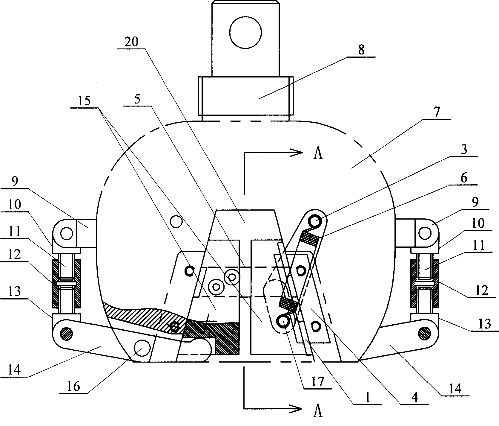
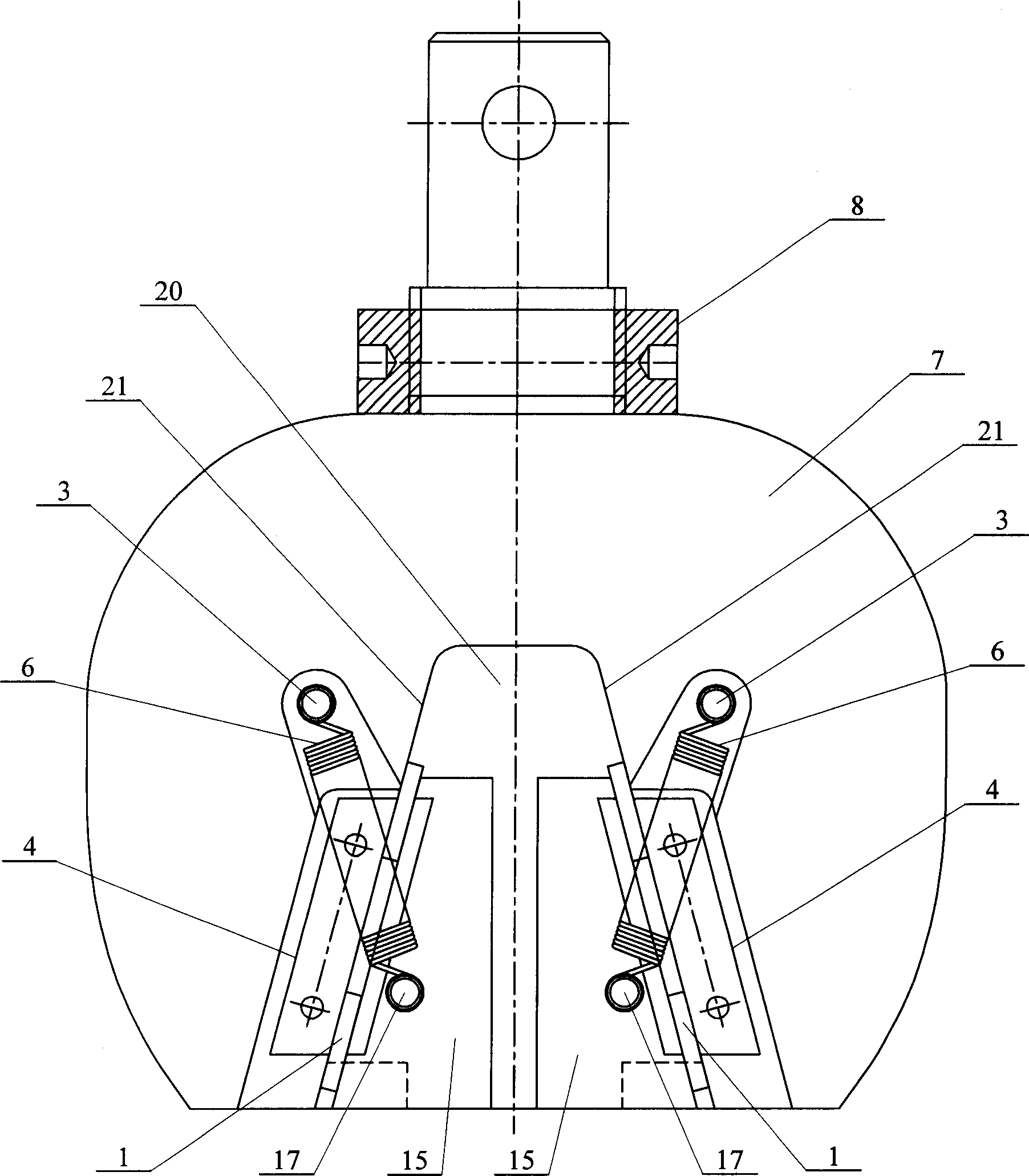
[0005] Specific implementation one: (see figure 1 ~ Figure 5) This embodiment is composed of upper / lower clamping body 7, nut 8, guide block 5, left pre-tightening device, right pre-tightening device, left half clamping device and right half clamping device. The side preloading force device and the right side preloading force device are symmetrically fixed on the left and right sides outside the upper / lower clamping body 7, and the left half clamping device and the right half clamping device are symmetrically arranged on the upper / lower clamping body 7 Inside, the nut 8 is arranged on the upper part of the upper / lower clamping body 7, and the left-side pre-tightening force device and the right-side pre-tightening force device are respectively formed by the support plate 9, the upper connecting body 10, the left-right screw 11, the left-right nut 12, and the lower The connecting body 13, the lever pressing plate 14 and the pin shaft 16 are composed. The upper connecting body 10...
specific Embodiment approach 2
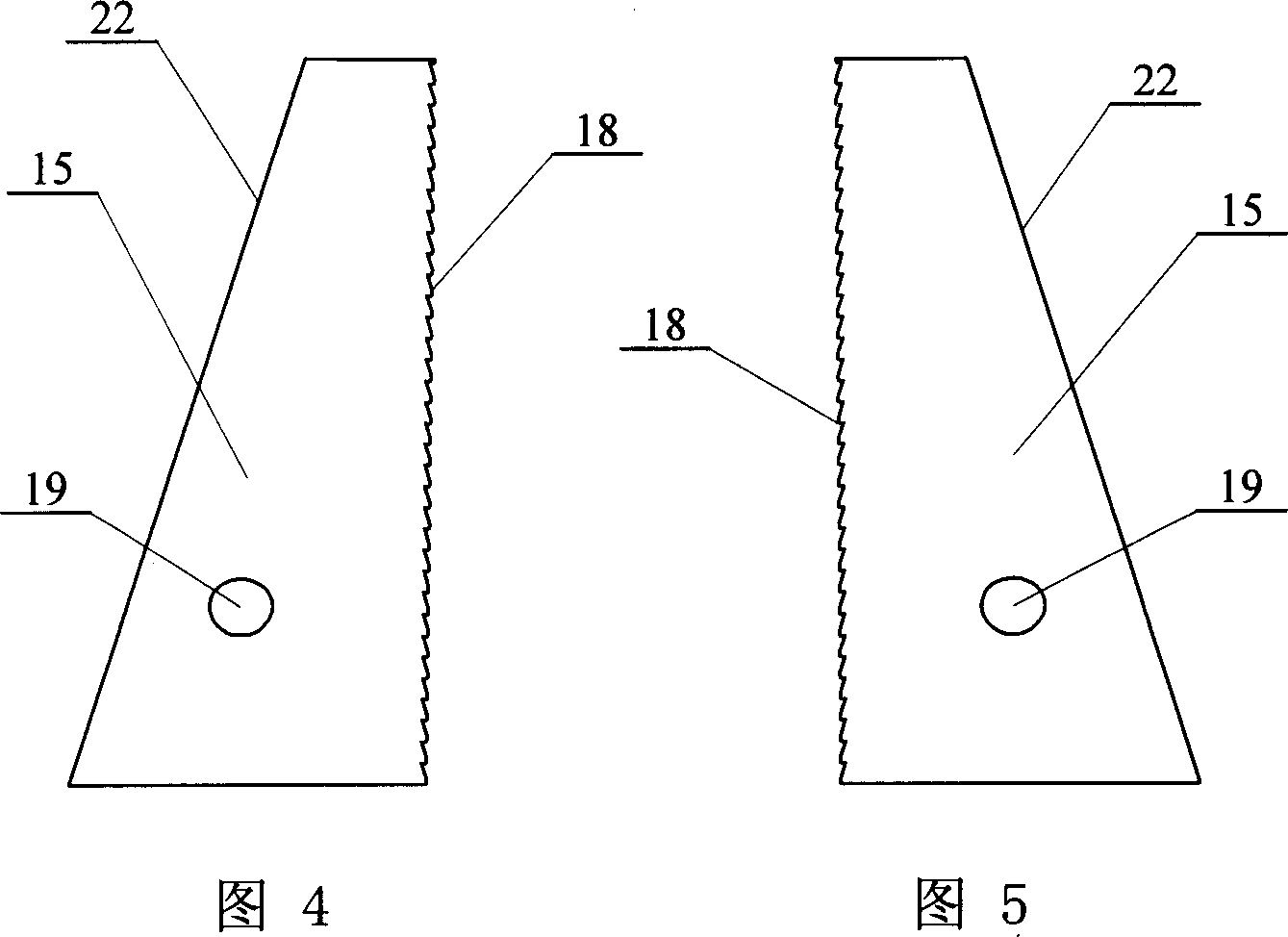
[0006] Specific implementation two: (see image 3 ~ FIG. 5 ) The difference between this embodiment and the specific embodiment 1 is that the contact surfaces of the two wedge-shaped sliders 15 in the left half clamping device and the right half clamping device are provided with sawtooth-shaped concavities and convexities 18 . Other components and connection relationships are the same as in the first embodiment. The contact surfaces of the two wedge-shaped sliders 15 are provided with saw-tooth-shaped concavities and convexities 18, so that the sheet material can be clamped more firmly, and the test data can be more accurate.
[0007] Working principle: The compression experiment of the sheet specimen is realized by the self-locking principle of the wedge-shaped slider. 1. Under normal conditions, the wedge-shaped sliders zero the gap between the wedge-shaped slider groups due to the action of the tension spring. 2. The guide block synchronizes the movement of the two wedge-...
PUM
 Abstract
Description
Claims
Application Information
 - R&D
- Intellectual Property
- Life Sciences
- Materials
- Tech Scout
- Unparalleled Data Quality
- Higher Quality Content
- 60% Fewer Hallucinations
Browse by: Latest US Patents, China's latest patents, Technical Efficacy Thesaurus, Application Domain, Technology Topic, Popular Technical Reports.
© 2025 PatSnap. All rights reserved.Legal|Privacy policy|Modern Slavery Act Transparency Statement|Sitemap|About US| Contact US: help@patsnap.com


