Eureka AIR delivers breakthrough ideas for toughest innovation challenges, trusted by R&D personnel around the world.

Broadband wave beam forming method and apparatus

A beam and broadband technology, applied in the field of broadband beam forming methods and devices, can solve the problems of voice enhancement performance degradation and the like

Inactive Publication Date: 2006-11-22
HUAWEI TECH CO LTD +1
View PDF0 Cites 25 Cited by
  • Summary
  • Abstract
  • Description
  • Claims
  • Application Information

AI Technical Summary

Problems solved by technology

[0028] The above-mentioned MVDR beamforming technology can only be applied to narrowband signal sources. When this method is used for broadband signal sources, its speech enhancement performance will be greatly reduced. Moreover, this technology can only be applied to far-field signal sources, that is, the incident signal is a plane wave , when this technology is applied to near-field signal sources, that is, when the incident signal is a spherical wave, the performance of speech enhancement will also drop significantly

Method used

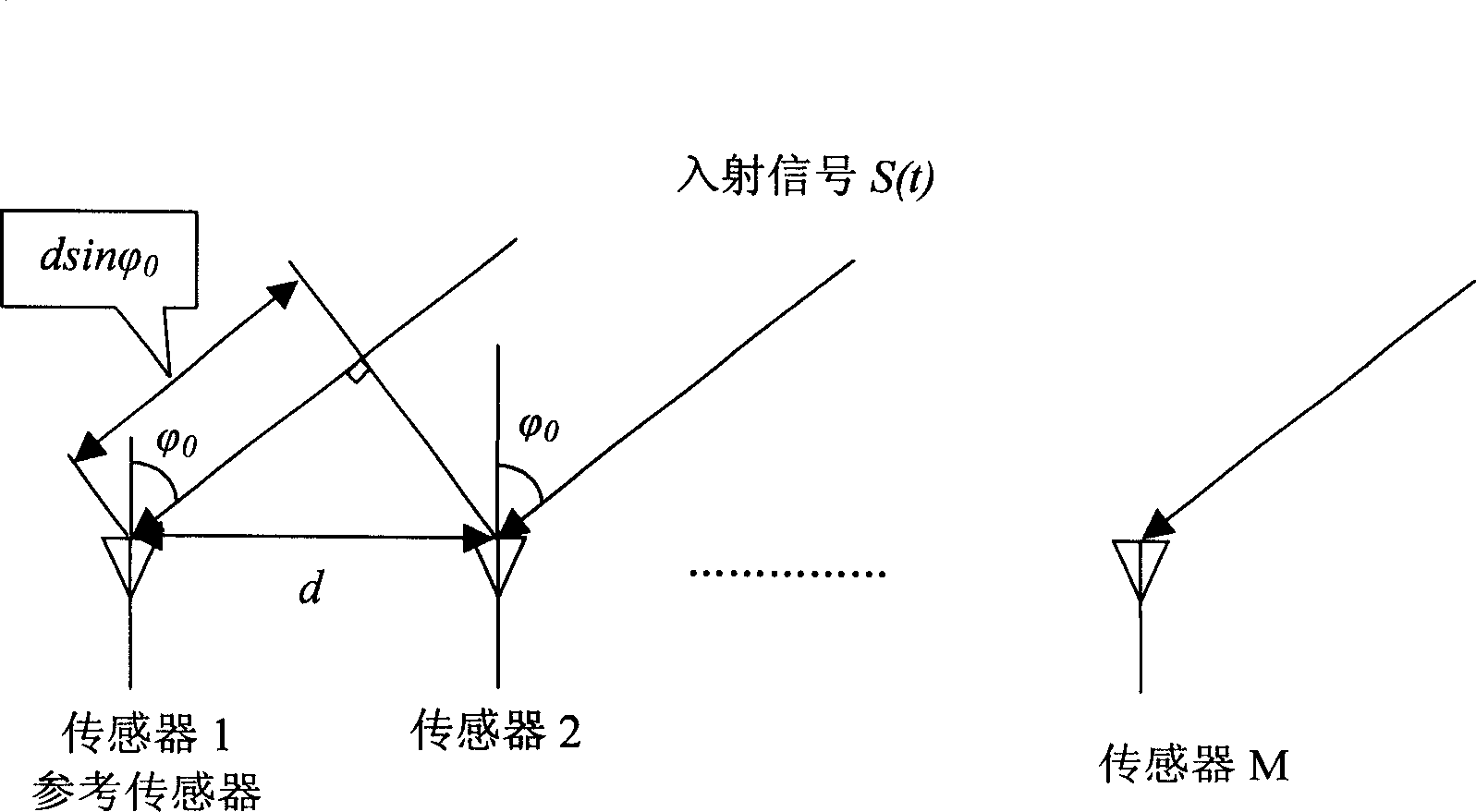
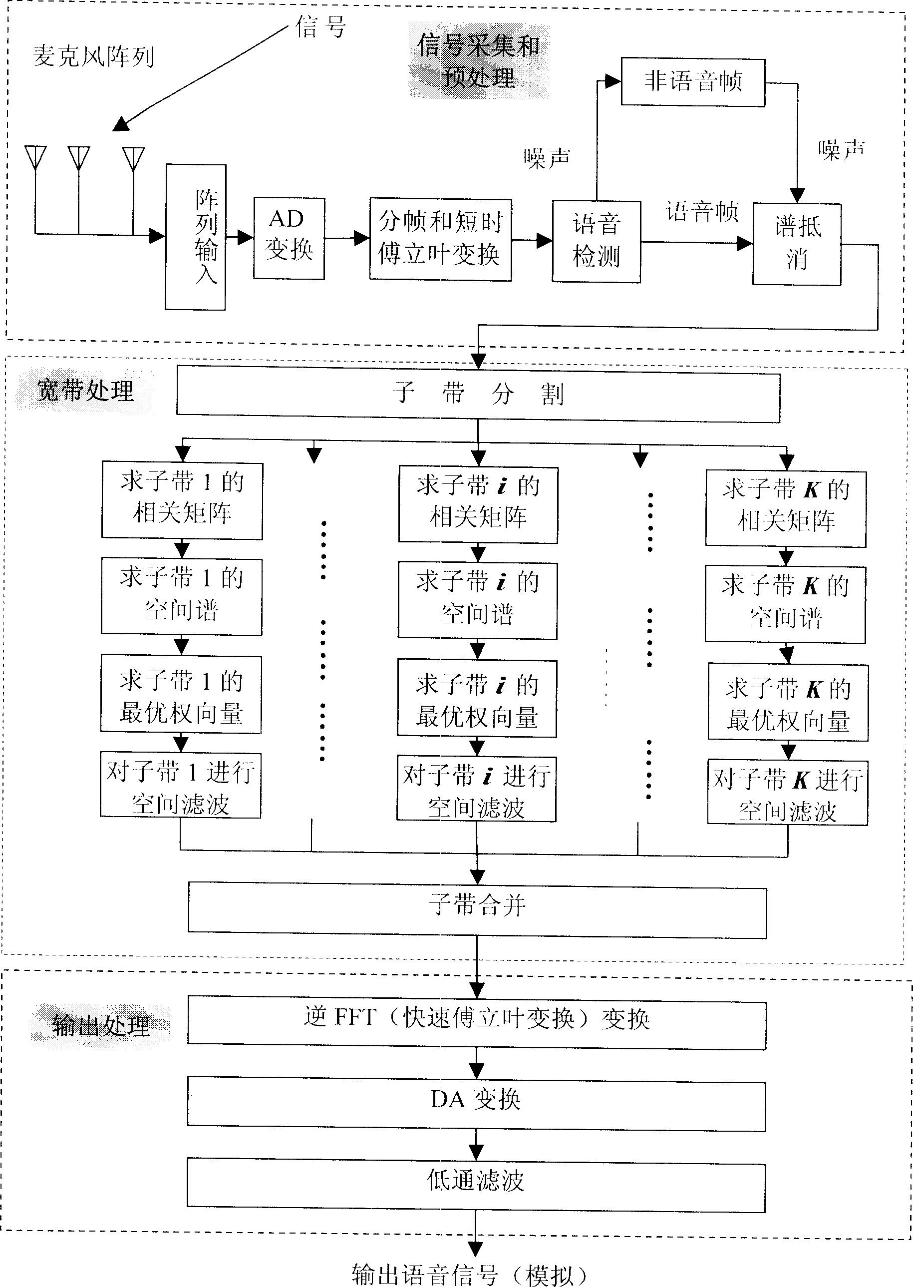
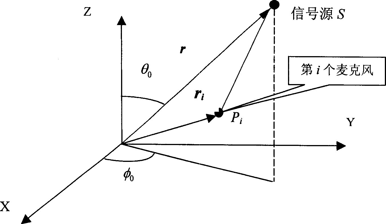

Image

  • Broadband wave beam forming method and apparatus
  • Broadband wave beam forming method and apparatus
  • Broadband wave beam forming method and apparatus

Examples


Embodiment Construction

[0098] The cores of the method and device of the present invention are as follows: determine each sub-band signal corresponding to the signal input to each microphone, determine the frequency-domain correlation matrix of each sub-band signal, and determine according to the three-dimensional space transmission vector of the signal source and each frequency-domain correlation matrix The weight vector of each sub-band signal determines the output signal according to the weight vector of each sub-band signal and each sub-band signal.

[0099] The technical solution provided by the present invention will be further described below based on the core idea of ​​the present invention.

[0100] The microphone type in the present invention is an omnidirectional microphone, and the sound pickup distance of the microphone can be determined according to the specific application environment, such as the room size is 5 meters long, 10 meters wide, and 4 meters high, if all the sounds in the ro...


PUM


Abstract

The disclosed forming method for broadband waveform comprises: determining the sub-band signal opposite to the microphone signal, as well as the signal frequency-domain correlation matrix; according to 3D space transmission vector of signal source and former matrix, determining the weight vector for every sub-band signal; then deciding the output signal. This invention combines frequency and space domain for speech process, and improves SNR for wide application.

Description

technical field [0001] The present invention relates to audio processing technology, in particular to a broadband beam forming method and device. Background technique [0002] With the vigorous development of modern science, communication or information exchange has become a necessary condition for the existence of human society, and speech, as the acoustic performance of language, is one of the most natural, effective and convenient means for human to exchange information. [0003] In the process of voice communication, it is inevitable to be interfered by the surrounding environment, the noise introduced by the transmission medium, the electrical noise inside the communication equipment, and even other speakers. These interferences will eventually make the voice received by the voice receiver no longer the pure original voice, but the noisy voice polluted by noise. For example, phones in cars, streets, and airports are often disturbed by strong background noise, which ser...

Claims


Application Information

Patent Timeline
IPC IPC(8): G10L21/0232
Inventor 居太亮邵怀宗林静然彭启琮余水安
Owner HUAWEI TECH CO LTD
Why Eureka
Eureka Blog
Learn More