MEMS microprobe and preparation method thereof

A micro-probe and mechanics technology, applied in the field of MEMS mechanical micro-probe and its preparation, can solve problems such as high price, and achieve the effects of being beneficial to online detection, convenient control and accurate detection

Inactive Publication Date: 2006-11-22
PEKING UNIV
View PDF0 Cites 13 Cited by
  • Summary
  • Abstract
  • Description
  • Claims
  • Application Information

AI Technical Summary

Problems solved by technology

Due to the limitations of traditional precision machining methods, there has been no easy-to-operate, low-cost, and effective solution for micro-force output and micro-displacement detection. At present, there are only nano-indentation instruments or similar equipment that are expensive and complicated to operate. able to perform such measurements

Method used


Image

  • MEMS microprobe and preparation method thereof
  • MEMS microprobe and preparation method thereof
  • MEMS microprobe and preparation method thereof

Examples


Embodiment Construction

[0040] Microprobe structure:

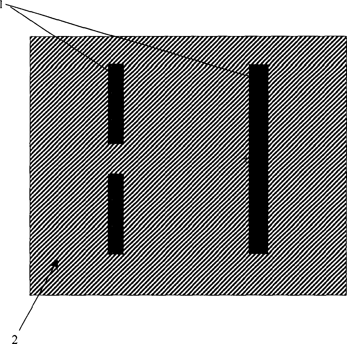
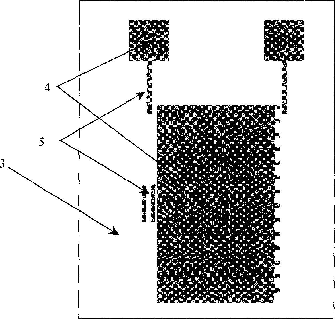
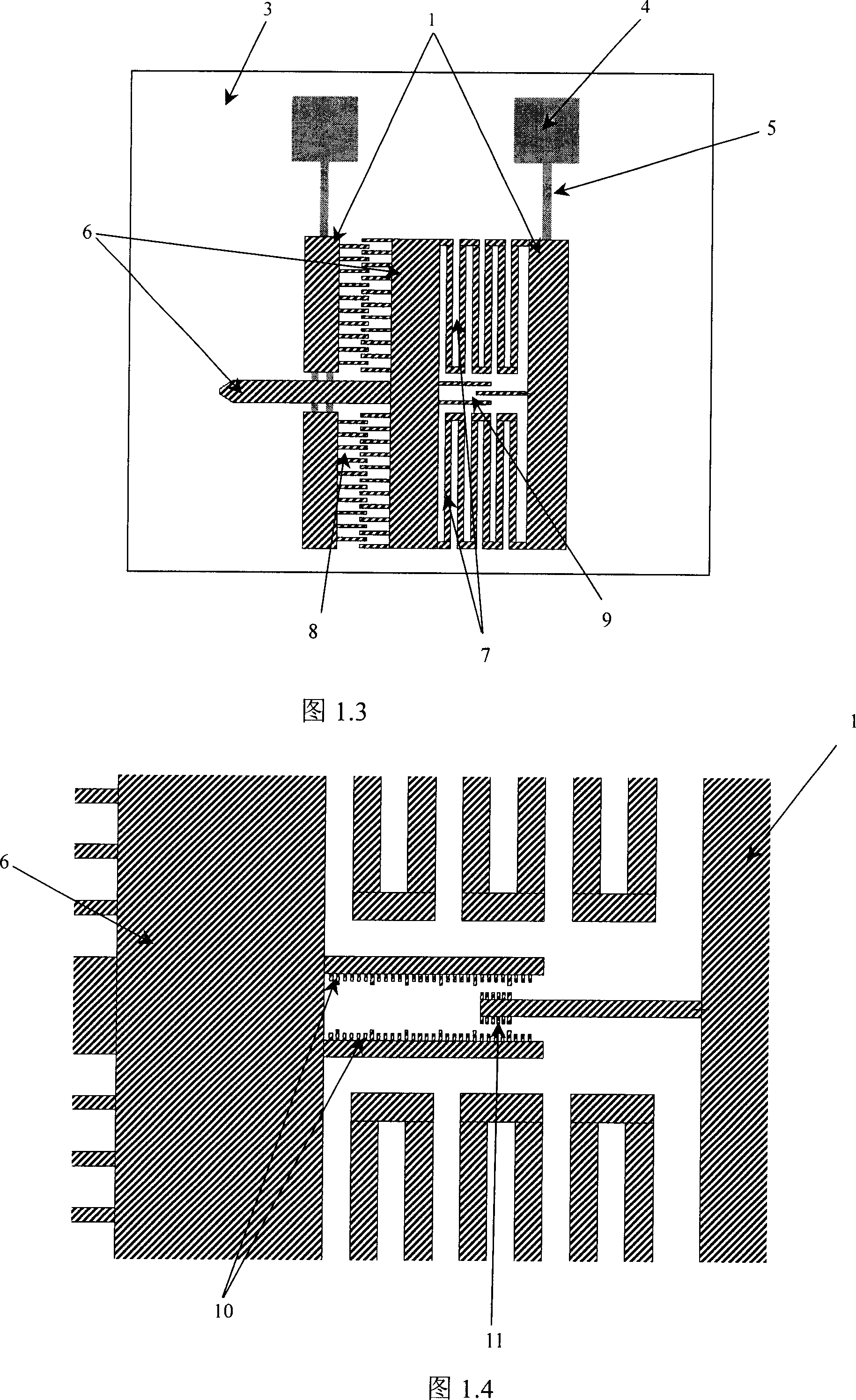
[0041] Refer to Figure 1.3, Figure 1.4, Figure 1.5 as well as Figure 2.4 , the microprobe structure of the present invention is generally divided into an upper monocrystalline silicon structure probe body and a lower glass structure substrate 3, and the upper monocrystalline silicon structure probe body part includes: a fixed anchor point (anchor) 1, a T-type probe Head 6, elastic beam structure 7, comb capacitor 8 and readout scale 9. The T-shaped probe head 6 is suspended on the substrate through the elastic beam 7 connected to the fixed anchor point 1. Two comb-toothed capacitors 8 are respectively arranged on the shoulder of the T-shaped probe head 6, and one side of the comb-toothed capacitor 8 The pole plate is connected to the fixed anchor point 1, and the other side plate of the comb capacitor 8 is connected to the T-shaped probe head 6. The scale structure includes: two parts: the moving ruler 10 and the fixed ruler 11, the moving ru...


PUM


Abstract

The disclosed MEMS mechanical microprobe comprises: a body composed by a T-shaped probe suspended above the substrate through the beam, an elastic beam fixed with riveted point, two comb capacitors fixed on the probe shoulders and connected to the riveted points by its positive / negative plates, and a scale structure with the slide and fixing parts lined to the probe and riveted point respectively. This invention is convenient to read and implement.

Description

technical field [0001] The invention belongs to the technical field of micro-electro-mechanical systems (MEMS) processing technology, and in particular relates to a MEMS mechanical microprobe and a preparation method thereof. Background technique [0002] As an interdisciplinary emerging technology developed in the 1990s, microelectromechanical system (MEMS) technology has an irreplaceable role in improving the quality of life and comprehensive national strength, and is an important means for many traditional industries to expand their technological content. The interdisciplinary characteristics of MEMS make it involve a wide variety of research fields and processing technologies in the development process. Among the many MEMS processing technologies, silicon-based processing technology has become the mainstream of MEMS processing technology commonly used by scientific researchers due to its advantages of high processing efficiency, low cost, and compatibility with integrate...

Claims


Application Information

Patent Timeline
Patent Type & Authority Applications(China)
IPC IPC(8): B81B1/00
Inventor 刘冬宁张大成贺学峰李婷杨芳王颖张美丽
Owner PEKING UNIV
Why Eureka
Try Eureka