
Accumulator charger and charging method thereof

A battery and charger technology, applied in the direction of secondary battery charging/discharging, battery circuit devices, current collectors, etc., can solve the problems of complex structure, temperature rise, and shortening of battery life.

Inactive Publication Date: 2006-11-22
JIANGSU TEACHERS UNIV OF TECH
View PDF1 Cites 13 Cited by
  • Summary
  • Abstract
  • Description
  • Claims
  • Application Information

AI Technical Summary

Problems solved by technology

[0002] The charging process of the battery is a very complicated electrochemical reaction process. Because the charging process, charging current and its changing law of the battery produced by each manufacturer are different, and the usual constant current smart charger is close to the end voltage when charging , has exceeded the range of the ideal charging curve and cannot meet the ideal charging requirements of the battery, causing the electrolyte of the battery to discharge a large amount of gas and increase the temperature of the battery, causing resistance polarization and concentration polarization of the battery, reducing the use of the battery Life, Chinese patent 88107780.1 discloses a "dynamic tracking intelligent fast charger", which uses microcomputer control, dynamic tracking fast charger structure to realize the charging process, but its structure is complicated, in the process of charging, due to the continuous The way of charging will increase the temperature of the battery, causing the resistance polarization and concentration polarization of the battery, which will reduce the service life of the battery

Method used


Image

  • Accumulator charger and charging method thereof
  • Accumulator charger and charging method thereof
  • Accumulator charger and charging method thereof

Examples


Embodiment Construction

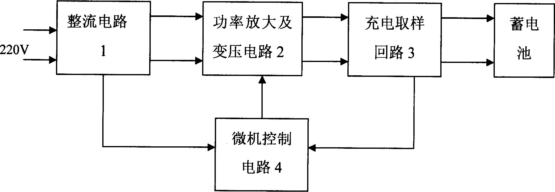
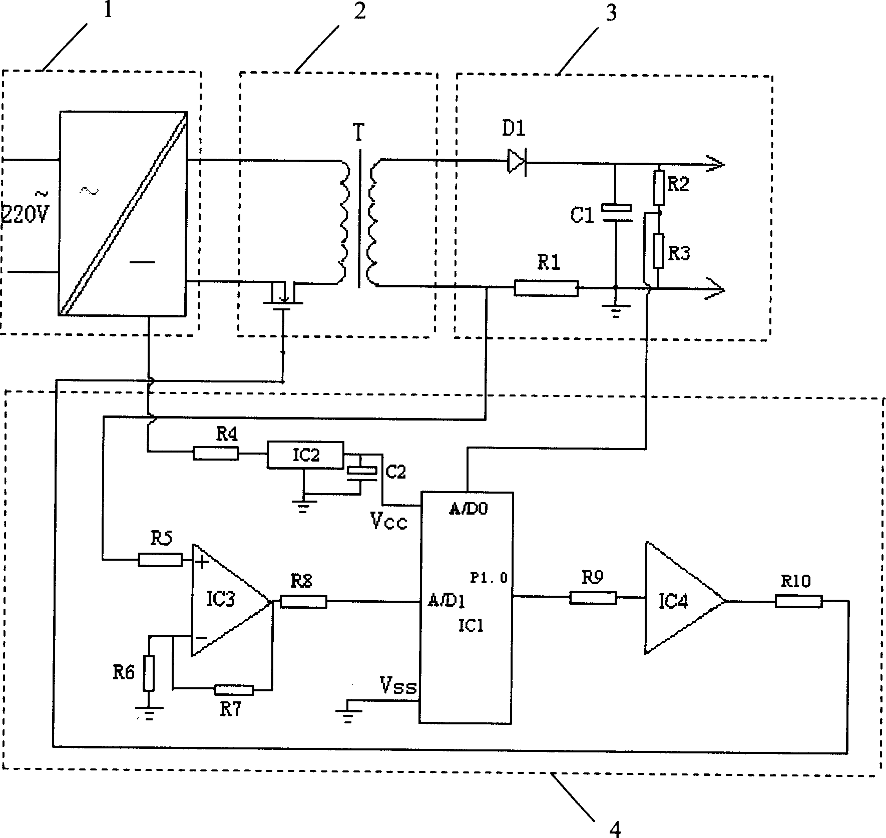
[0013] See figure 1 , the battery charger of the present invention includes a rectification circuit 1, a pulse power amplification and voltage transformation circuit 2, a charging sampling circuit 3 and a microcomputer control circuit 4; One output end is connected with the input end of the pulse power amplification and voltage transformation circuit 2, the output end of the pulse power amplification and voltage transformation circuit 2 is connected with the input end of the charging sampling circuit 3, and the output end of the charging sampling circuit 3 is connected with the battery to be charged. The two ends are connected, the sampling output end of the charging sampling circuit 3 is connected with one input end of the microcomputer control circuit 4, and the other output end of the rectification circuit 1 is connected with the power supply end of the microcomputer control circuit 4.

[0014] See figure 2 The microcomputer control circuit 4 includes a single-chip microc...


PUM


Abstract

The invention discloses an accumulator charger and charging method, which comprises the following parts: commutating circuit, pulse power amplification and transformation circuit, charging sampling circuit and microcomputer control circuit. The charger uses down rectangular wave pulse charging to produce segment charging peak current within ideal curved scale, which eliminates accumulator resistance polarization and concentration polarization of common intelligent charger. When the pulse down segment stops charging, the accumulator possesses enough cooling restoring time. The invention realizes rapid charging, which lengthens utility lifetime of accumulator.

Description

technical field [0001] The invention relates to a storage battery charger and a charging method. Background technique [0002] The charging process of the battery is a very complicated electrochemical reaction process. Because the charging process, charging current and its changing law of the battery produced by each manufacturer are different, and the usual constant current smart charger is close to the end voltage when charging , has exceeded the range of the ideal charging curve and cannot meet the ideal charging requirements of the battery, causing the electrolyte of the battery to discharge a large amount of gas and increase the temperature of the battery, causing resistance polarization and concentration polarization of the battery, reducing the use of the battery Life, Chinese patent 88107780.1 discloses a "dynamic tracking intelligent fast charger", which uses microcomputer control, dynamic tracking fast charger structure to realize the charging process, but its stru...

Claims


Application Information

Patent Timeline
IPC IPC(8): H02J7/00H01M10/44H02J7/02H02J7/04H02J7/10
CPCY02E60/10
Inventor 杨龙兴
Owner JIANGSU TEACHERS UNIV OF TECH
Learn More