Self-purging unit for filter screen of air conditionner
A filter and self-cleaning technology, which can be applied to space heating and ventilation details, household heating, lighting and heating equipment, etc., can solve the problems of difficult processing technology and high cost, and achieve low cost, excellent performance and ingenious design Effect
- Summary
- Abstract
- Description
- Claims
- Application Information
AI Technical Summary
Problems solved by technology
Method used
Image

Examples
Embodiment 1
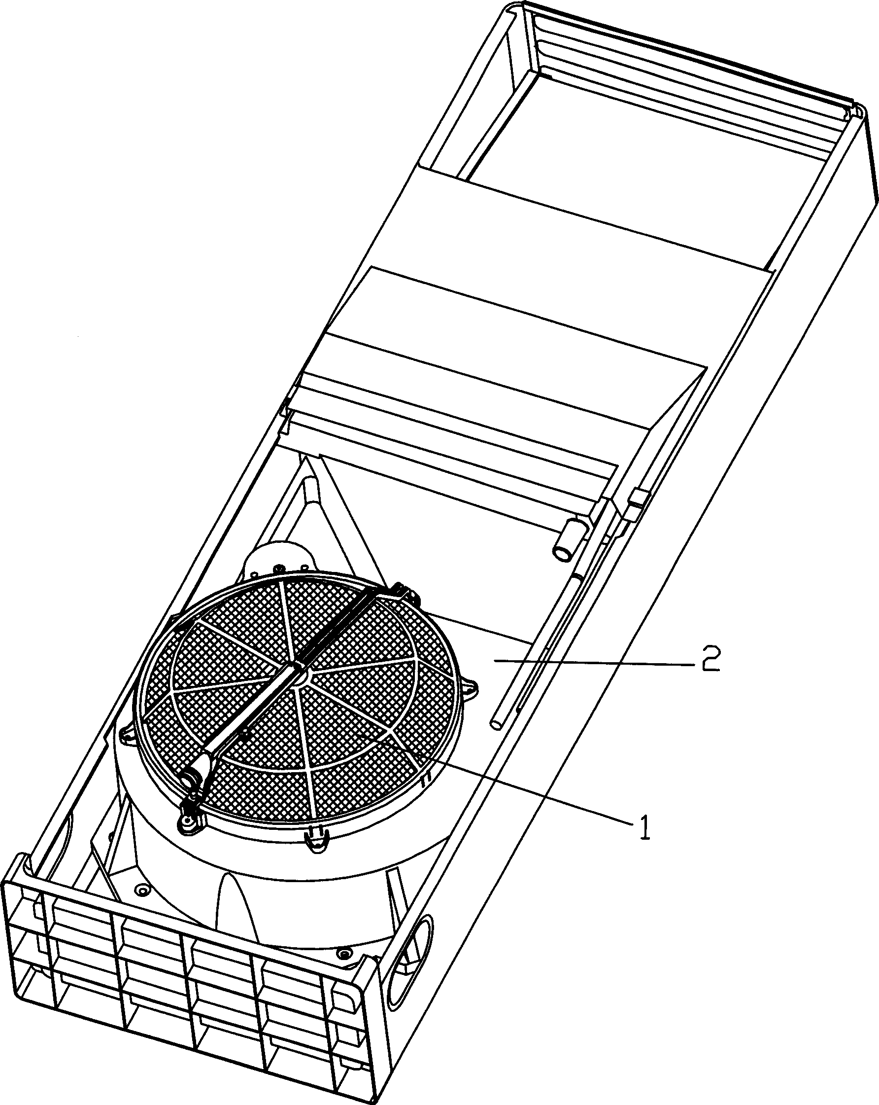
[0047] The structure diagram of the present invention is as figure 1 As shown, the self-cleaning device 1 is placed on the front side of the air inlet of the air duct volute 2 of the indoor unit of the air conditioner, and the filter in the device can wrap around the air duct volute in the space between the air duct volute and the air inlet grille. The center of the air inlet rotates. During the operation of the air conditioner, the air is sucked into the air duct volute by the fan through the filter screen of the self-cleaning device, and then blown into the room after passing through the heat exchanger, and the dust in the air is adsorbed on the air filter screen. After running for a period of time, the dust on the filter net can be sucked away by the self-cleaning device and discharged outside.
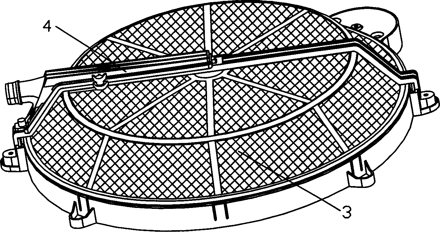
[0048] figure 2 It is a partial structural diagram of the self-cleaning device. The whole device is composed of three parts, one is the suction nozzle mechanism 4, the other is ...
Embodiment 2
[0060] The structure of the present invention is the same as that of Embodiment 1, the difference is that the suction nozzle mechanism is different, Figure 13 It is a schematic diagram of the structure of the suction nozzle mechanism. A dust sweeping brush 22 is arranged along the dust suction port 5 on the suction nozzle mechanism. The accumulated dust of removing can be swept away by sweeping the dust brush 22. This method of sweeping dust with a brush makes the dust on the filter net firstly sucked by the suction port on the nozzle bracket, and the dust that is difficult to suck can be brushed off from the back with the dust brush, which can improve the overall The dust removal effect of the device.
Embodiment 3
[0062] The structure of the present invention is the same as Embodiment 1, the difference is that the self-cleaning device 1 is different, Figure 14 And Figure 15 shows another structure of self-cleaning device, in this embodiment, the shape of the filter net frame and the suction nozzle has been greatly changed compared with the above-mentioned embodiment, the filter net frame 11 adopts the form of a round cover , that is, the cross section is an arch. Correspondingly, the suction nozzle 10 is also designed as an arched structure with a suitable radian, so that the suction port 5 is in close contact with the air filter 3 . Same as embodiment 1, the suction nozzle mechanism does not move, and the filter screen rotates together with the grid frame.
PUM
 Abstract
Description
Claims
Application Information
 - R&D
- Intellectual Property
- Life Sciences
- Materials
- Tech Scout
- Unparalleled Data Quality
- Higher Quality Content
- 60% Fewer Hallucinations
Browse by: Latest US Patents, China's latest patents, Technical Efficacy Thesaurus, Application Domain, Technology Topic, Popular Technical Reports.
© 2025 PatSnap. All rights reserved.Legal|Privacy policy|Modern Slavery Act Transparency Statement|Sitemap|About US| Contact US: help@patsnap.com