Full wave bridge type circuit of synchronous rectification

A technology for synchronous rectification and shaping circuits, which is applied in the direction of electrical components, AC power input conversion to DC power output, output power conversion devices, etc., and can solve problems such as circuits that cannot work independently, complicated circuit operations, and complicated circuit structures. To achieve the effect of expanding the use range, temperature rise and low cost

Inactive Publication Date: 2006-12-06
EAGLERISE ELECTRIC & ELECTRONICS (CHINA) CO LTD
View PDF1 Cites 15 Cited by
  • Summary
  • Abstract
  • Description
  • Claims
  • Application Information

AI Technical Summary

Problems solved by technology

[0005] Although this circuit can also achieve the purpose of synchronous rectification required by low voltage and high current, it has the following shortcomings: (1) The circuit is complicated and the cost is high
No matter what kind of structure it is, because the number of electronic components required is too large, the structure of the circuit will be complicated and the cost will be high
(2) Very inconvenient to use
like figure 1 , figure 2 As shown, when the operational amplifier works normally for level comparison, it must need a DC auxiliary power supply V dd , that is to say, the circuit can not work independently, it must be provided by line conversion or other devices to provide DC power V dd Only with the assistance of

Method used


Image

  • Full wave bridge type circuit of synchronous rectification
  • Full wave bridge type circuit of synchronous rectification
  • Full wave bridge type circuit of synchronous rectification

Examples


Embodiment Construction

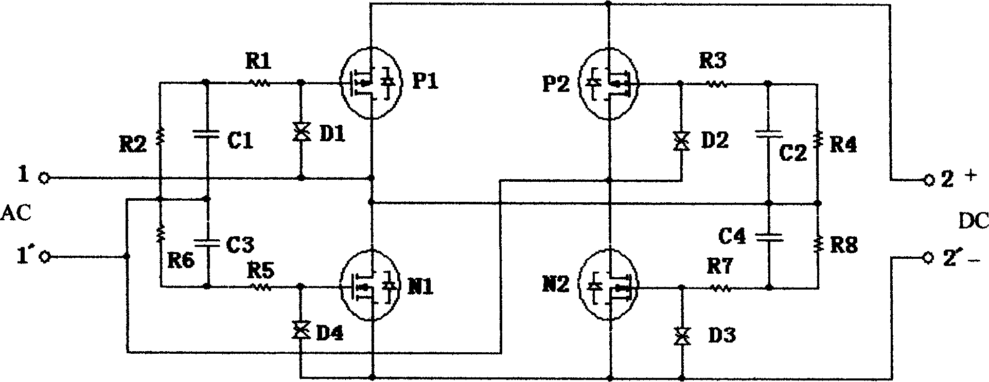
[0019] The specific working process of the embodiment of the present invention will be further described below in conjunction with the accompanying drawings.

[0020] Such as image 3 As shown, the full-wave bridge synchronous rectification circuit is composed of four MOSFETs, two of which are NMOSFET tubes N1 and N2, two of which are PMOSFET tubes P1 and P2, and: two special-shaped tubes N1 and P1 The drain is electrically connected to the 1 terminal of the AC input voltage; the drains of the two special-shaped tubes N2 and P2 are electrically connected to the 1' terminal of the AC input voltage; the sources of the two same-shaped tubes N1 and N2 are electrically connected to the DC output voltage terminal 2 of the same type tubes; the sources of the two tubes P1 and P2 are electrically connected to the terminal 2' of the DC output voltage. Bidirectional Zener Diode D 1 Connected between the gate and source of PMOS transistor P1; bidirectional voltage regulator diode D 2 C...


PUM


Abstract

The rectification circuit includes following parts: synchronous rectification MOS tubes connected to bridge type rectification circuit; being connected between grid and source electrodes of corresponding synchronous rectification MOS tubes, the voltage amplitude limited components in use for limiting amplitude of drive voltage led from AC input end in order to insure safety of operation of corresponding MOS tubes; being connected between one terminal of AC input voltage and a relevant grids of synchronous rectification MOS tubes, shaping circuit of driving voltage in use for carrying out wave shaping for drive voltage led from AC input end in order to turn MOS tubes on/off in correct time. Features are: simple structure, independent use, and long wire of load. The invention is widely applicable to high frequency, low voltage synchronous rectification circuit in switch mode for output of power supply.

Description

technical field [0001] The invention relates to a synchronous rectification circuit, in particular to a full-wave bridge synchronous rectification circuit. Background technique [0002] In recent years, with the development of electronic technology, many occasions require the working voltage of the circuit to be lower and lower, and the current is higher and higher. In the case of requiring output DC low voltage and high current, even if a Schottky diode (SBD) with low conduction voltage drop is used as a rectifier device, a voltage drop of about 0.5V will be generated. If the current reaches 10A, or even 20A Above, the tube consumption of a rectifier diode will reach about 10W. The tube consumption is very prominent, which makes the rectification output efficiency of the power supply extremely low. Therefore, the traditional diode rectification circuit can no longer meet the needs of realizing low voltage and high current rectification. [0003] Synchronous rectification...

Claims


Application Information

Patent Timeline
Patent Type & Authority Applications(China)
IPC IPC(8): H02M7/219
Inventor 肖俊承邹高迪
Owner EAGLERISE ELECTRIC & ELECTRONICS (CHINA) CO LTD
Why Eureka
Try Eureka