Tool holding structure

A clamping structure and tool technology, applied in the direction of clamping, tool manufacturing, support, etc., can solve the problems of tool holder installation orientation error, danger, etc., and achieve the effect of simple structure, improved reliability, and precise tool clamping

Inactive Publication Date: 2006-12-20
FANUC LTD
View PDF1 Cites 11 Cited by
  • Summary
  • Abstract
  • Description
  • Claims
  • Application Information

AI Technical Summary

Problems solved by technology

As a result, there is a risk of causing errors in the installation orientation of the tool holder due to the insertion angle, etc.

Method used


Image

  • Tool holding structure
  • Tool holding structure
  • Tool holding structure

Examples


Embodiment Construction

[0020] Embodiments of the present invention will be described in detail below with reference to the accompanying drawings.

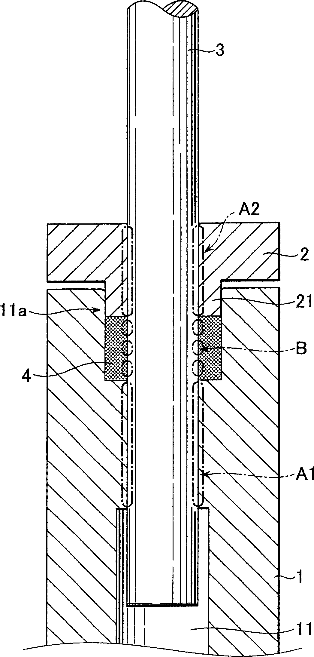
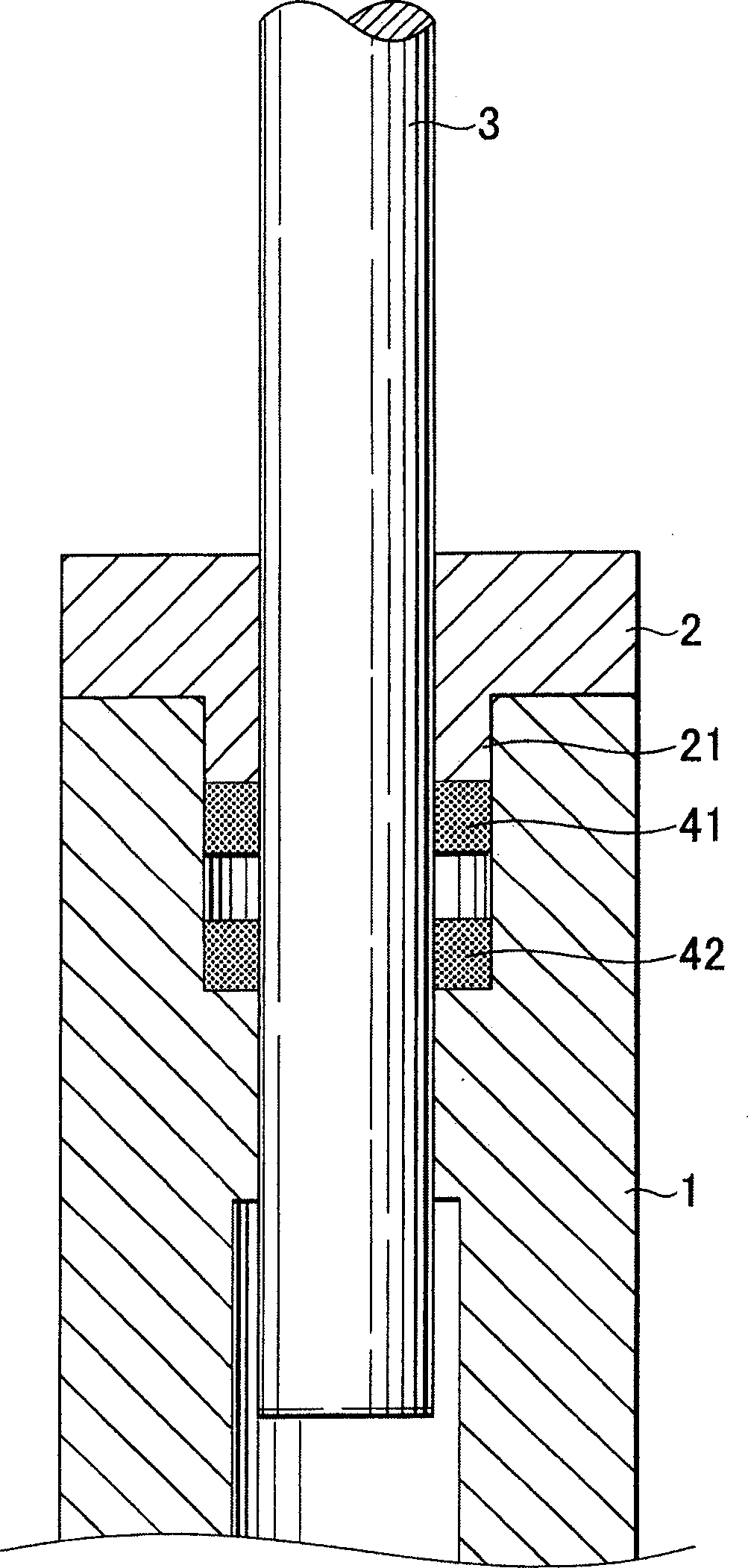
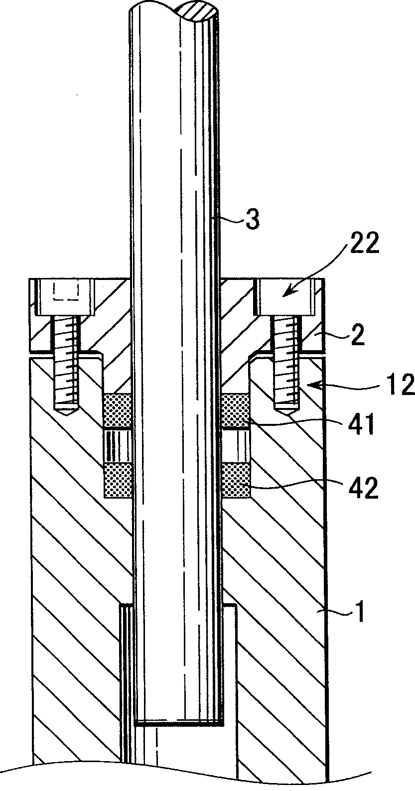
[0021] figure 1 is a sectional view showing a section along the axis of the main shaft, showing main parts of a tool holding structure according to an embodiment of the present invention. exist figure 1 In , reference numeral 1 denotes a main shaft of a machine tool, and main shaft 1 has a tool shank insertion hole 11 extending in the axial direction of main shaft 1 . Reference numeral 2 denotes a sleeve coaxially mounted on the main shaft 1 , the sleeve 2 having an insertion portion 21 inserted into a large diameter portion 11 a formed on the entry side of the shank insertion hole 11 .

[0022] Both the shape and size of the inner peripheral surface of the large-diameter portion 11a and the outer peripheral portion of the insertion portion 21 are precisely matched to each other. The sleeve 2 also has a through hole through which the tool shank 3 pass...


PUM


Abstract

The invention provides a simplified holding structure for a tool for a machine tool that makes accurate tool holding possible. The tool shank is inserted through a through hole of a sleeve and into a tool shank insertion hole. The sleeve insertion part is inserted into a large-diameter part and fixed coaxially to the spindle with bolts or the like, so as to axially compress at least one annular elastic member provided on the large-diameter part. A first shank-supporting portion is provide inside the tool shank insertion hole and a second shank-supporting portion is provided on the sleeve through hole. A front end part of the insertion part is semicircular or trapezoidal in axial cross-section. The tool shank insertion hole, the sleeve through hole and the annular elastic member have cross-sections in directions perpendicular to the axis of the tool shank shaped that match the tool shank.

Description

technical field [0001] The invention relates to tool clamping of a machine tool, in particular to a tool clamping structure for clamping and clamping a tool shank to the main shaft of a machine tool. Background technique [0002] In the prior art, collet chucks and hydraulic chucks are widely used for tool clamping of machine tools. However, when a collet type chuck is used, it is easy to cause a tool installation error, which depends on the dimensional accuracy of the collet and the tapered part of the spindle. Additionally, installing a hydraulic chuck-like mechanism on a small, high-speed spindle is impractical due to the design difficulties involved. In addition, various technologies related to tool clamping of machine tools have been proposed and disclosed in patent publications. [0003] JP11-77413A is a typical example, which discloses a bellows-shaped holder for holding a tool. The bellows-shaped holder has an outer peripheral surface surrounded by a holding membe...

Claims


Application Information

Patent Timeline
Patent Type & Authority Applications(China)
IPC IPC(8): B23Q3/12B23B31/08
CPCB23B31/1175Y10T409/309464
Inventor 河合知彦蛯原建三大木武
Owner FANUC LTD
Why Eureka
Try Eureka