
Optical channel performance on-line monitoring module

A technology for monitoring modules and optical channels, applied in electromagnetic wave transmission systems, electrical components, transmission systems, etc., can solve problems such as insufficient stability and reliability, difficult installation and adjustment, etc.

Inactive Publication Date: 2006-12-20
INST OF SEMICONDUCTORS - CHINESE ACAD OF SCI
View PDF0 Cites 4 Cited by
  • Summary
  • Abstract
  • Description
  • Claims
  • Application Information

AI Technical Summary

Problems solved by technology

[0004] The purpose of the present invention is to overcome the shortcomings of other spectrometers or detection instruments that the independent work of each component is not stable enough and difficult to install and adjust, and to provide a device with good stability, reliability, convenient and simple assembly and adjustment, and is convenient for standardization and large-scale production. Optical channel performance online monitoring module

Method used


Image

  • Optical channel performance on-line monitoring module
  • Optical channel performance on-line monitoring module
  • Optical channel performance on-line monitoring module

Examples


Embodiment Construction

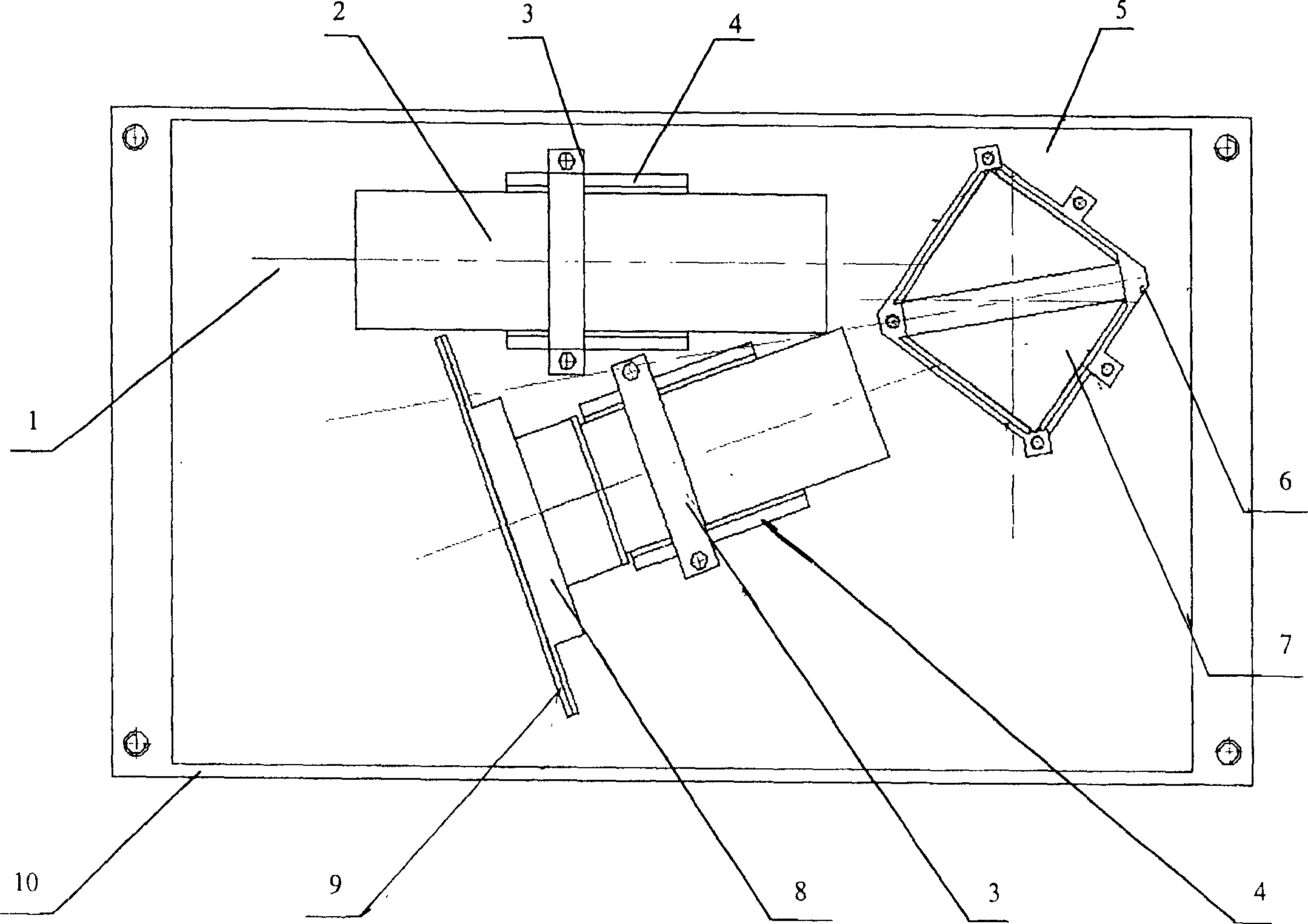
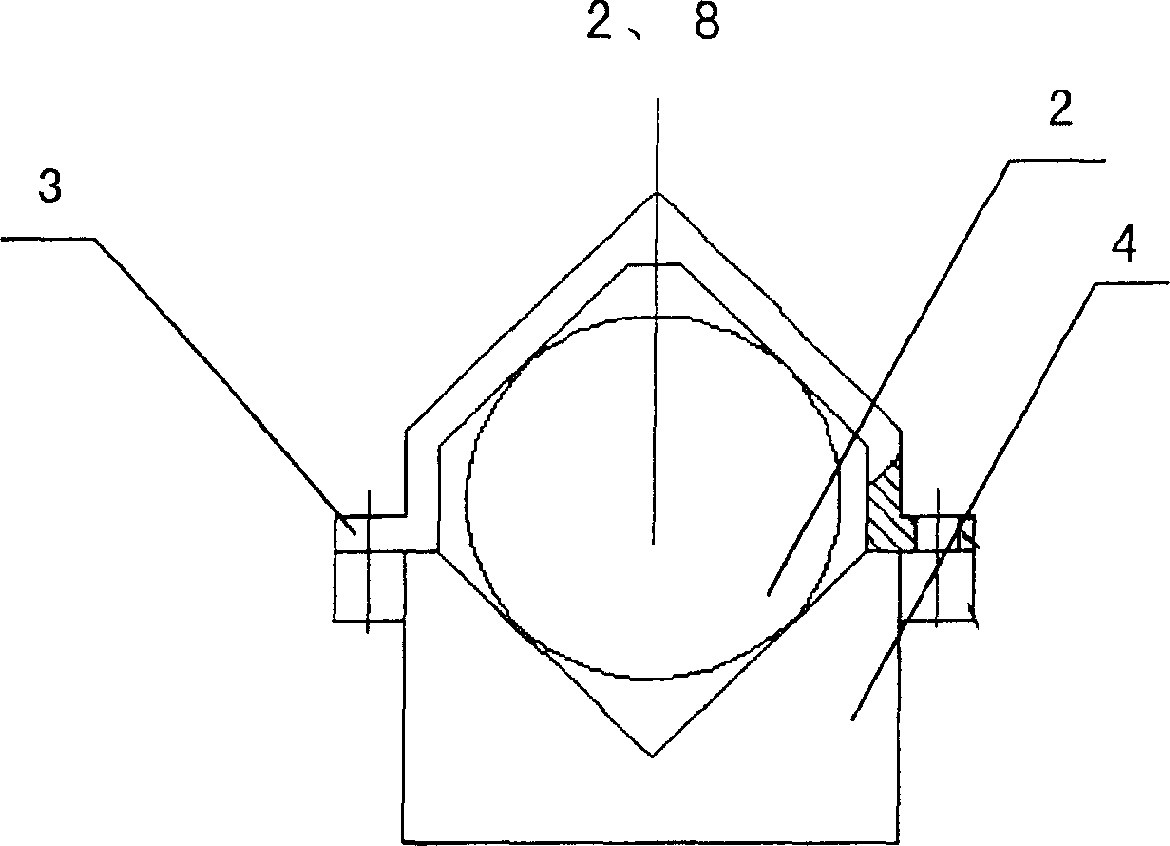
[0025] See figure 1 , An online monitoring module for optical channel performance of the present invention includes:

[0026] One input optical fiber 1, which is a standard single-film optical fiber;

[0027] A base 10, the base 10 is in the shape of a rectangular plate;

[0028] A collimating lens 2, the collimating lens 2 has a fiber input interface, the input fiber 1 is connected to the fiber input interface of the collimating lens 2, the collimating lens 2 is fixed on one side of the base 10;

[0029] A grating stage 6, the grating stage 6 is quadrilateral, the grating stage 6 has a rectangular groove in the middle, and the grating stage 6 is fixed on the base 10 at one end of the collimating lens 2;

[0030] A diaphragm 5, the two sides of the diaphragm 5 are at right angles, the diaphragm 5 has a light entrance and a light exit, the diaphragm 5 is fixed on the outside of the groove on the grating table 6;

[0031] The integrated holographic grating 7, the volume holographic...


PUM


Abstract

The invention relates to an optical channel property on-line detecting module, which comprises: an input optical fiber which is a standard single-mode optical fiber; a base which is a rectangle plate; a collimation lens with an interface of optical fiber input while said input optical fiber is connected to said optical fiber input interface and said collimation lens is fixed at one side of base; a grating table which is trapeziform and its middle has one rectangle groove; said grating table is fixed on the base at one end of collimation lens; a diaphragm whose two surface form right angle while its has a light inlet and a light outlet; said diaphragm is fixed at the outer side of groove of grating table; a solid holographic grating fixed inside the groove of grating table; a light receive interface fixed on the base at one side of collimation lens; a photodetection detecting array fixed at the end of light receive interface; and a top cover which is a rectangle frame covering the base and fixed on the base.

Description

Technical field [0001] The invention is an on-line monitoring instrument for optical channel performance in an optical communication network, is a key component of an intelligent optical network, and is also widely used in the field of spectrum analysis. Background technique [0002] With the widespread application of DWDM optical networks, the operating conditions of the DWDM system can be monitored effectively and in real time, so as to obtain the wavelength drift, power fluctuation, signal-to-noise ratio of each channel and other information that may cause data errors and transmission failures. It has gradually become an indispensable part in the construction of intelligent optical networks. The traditional optical network detector only detects the total optical power of all channels, and cannot monitor the operating conditions of each channel in the DWDM system and the amplifiers, multiplexers, optical switches, optical fibers themselves and optical fiber connections in the s...

Claims


Application Information

Patent Timeline
Patent Type & Authority Applications(China)
IPC IPC(8): H04B10/08H04J14/02H04B10/075
Inventor 曹彭辛红丽李芳刘育梁
Owner INST OF SEMICONDUCTORS - CHINESE ACAD OF SCI
Learn More