Impeller for compressor

A compressor impeller and impeller technology, applied in the field of compressor impellers, can solve the problems of increased loss at the outlet of the impeller 102 and reduced efficiency of the diagonal flow compressor 200, etc.

Inactive Publication Date: 2006-12-27
MITSUBISHI HEAVY IND LTD
View PDF1 Cites 4 Cited by
  • Summary
  • Abstract
  • Description
  • Claims
  • Application Information

AI Technical Summary

Problems solved by technology

[0008] in addition, Figure 14B The same phenomenon occurs in the impeller 200 of the shown oblique flow compressor, especially in the oblique flow compressor, since the force F2 to separate the flow from the hub surface 12c acts all the way to the outlet of the impeller where the hub surface 12c is inclined 102, so until the impeller outlet 102, the flow velocity distortion caused by the expansion of the boundary layer remains, and the loss at the impeller outlet 102 increases, resulting in a decrease in the efficiency of the mixed flow compressor 200

Method used


Image

  • Impeller for compressor
  • Impeller for compressor
  • Impeller for compressor

Examples


Embodiment Construction

[0086] Hereinafter, referring to Fig. 1A- Figure 1C A first embodiment of the compressor impeller of the present invention will be described. A specific example of the case where the impeller of this embodiment is applied to a centrifugal compressor is shown.

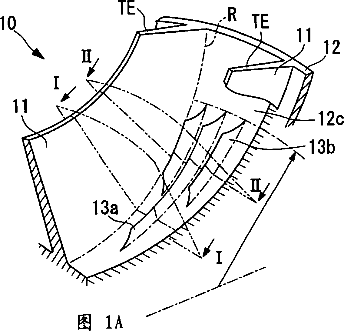
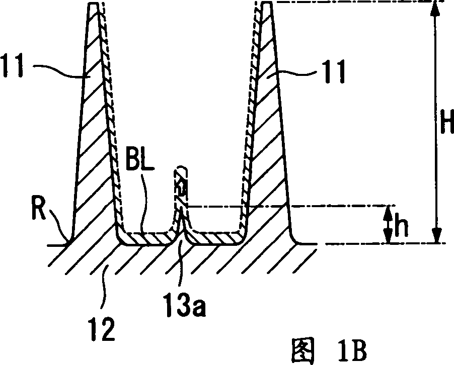
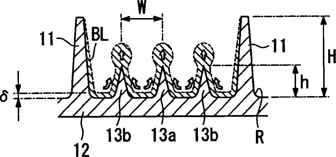
[0087] FIG. 1A is a perspective view of main parts of the impeller 10 according to this embodiment, and the end of the impeller 10 on the inlet side is omitted. In addition, FIG. 1B is a sectional view taken along the line I-I of FIG. 1A , Figure 1C It is a cross-sectional view taken along the line II-II in FIG. 1A .

[0088] Figure 1A~ Figure 1C As shown, the main constituent elements of the impeller 10 according to this embodiment include a plurality of blades 11 and a hub 12 disposed on the roots R of the blades 11 .

[0089]The blades 11 are respectively arranged on the surface of the hub 12 such that the leading edge LE thereof is positioned at the small diameter side end 12a of the hub 12, and the trailing ...


PUM


Abstract

An object is to improve the efficiency of a compressor by preventing localized concentration of a boundary layer occurring on the surface of a hub, and by inducing a reduction in the thickness of the boundary layer. There is a compressor impeller having a plurality of blades, and a hub disposed at the root of this plurality of blades, and in which at least part of the surface of the hub on which a fluid flows is inclined in relation to an axis of rotation, wherein a boundary layer reduction part which induces a reduction in the thickness of a boundary layer occurring due to a flow of fluid is provided on the surface of the hub.

Description

technical field [0001] The present invention relates to an impeller of a centrifugal compressor and a diagonal flow compressor, and is used in, for example, a gas turbine for aviation, a turbocharger for ships, a supercharger for automobiles, and the like. Background technique [0002] At present, little attention has been paid to the surface of the hub of the impeller used in the centrifugal compressor and the diagonal flow compressor, and no research has been carried out. So far, no research has been performed on the surface of the hub of the impeller. (For example: refer to Patent Document 1) [0003] Patent Document 1: JP-A No. 55-35173 [0004] Therefore, the inventors of the present application focused their studies on the hub surface of the rotating impeller, and as a result, it was found that the following phenomenon occurred on the hub surface. [0005] For example, in Figure 14A In the impeller 100 of the centrifugal compressor shown, when the blade 11 of the im...

Claims


Application Information

Patent Timeline
IPC IPC(8): F04D29/28
Inventor 东森弘高久间启司住田邦夫小田彻
Owner MITSUBISHI HEAVY IND LTD
Why Eureka
Try Eureka