Radiating system

A heat dissipation system and heat sink technology, applied in cooling/ventilation/heating transformation, instrumentation, electrical digital data processing, etc., can solve the problems of fan speed noise, single heat dissipation form, water-cooled heat dissipation device cannot dissipate heat from electronic circuit boards, etc. To achieve the effect of improving heat dissipation efficiency

Inactive Publication Date: 2007-01-10
GIGA BYTE TECH CO LTD
View PDF0 Cites 9 Cited by
  • Summary
  • Abstract
  • Description
  • Claims
  • Application Information

AI Technical Summary

Problems solved by technology

[0009] The technical problem to be solved by the present invention is to provide a heat dissipation system to solve the problem that the existing technology adopts a single heat dissipation form, the noise caused by the excessively high fan speed and the water-cooled heat dissipation device cannot dissipate heat on the electronic circuit board where the electronic components are located. technical issues

Method used


Image

  • Radiating system
  • Radiating system
  • Radiating system

Examples


Embodiment Construction

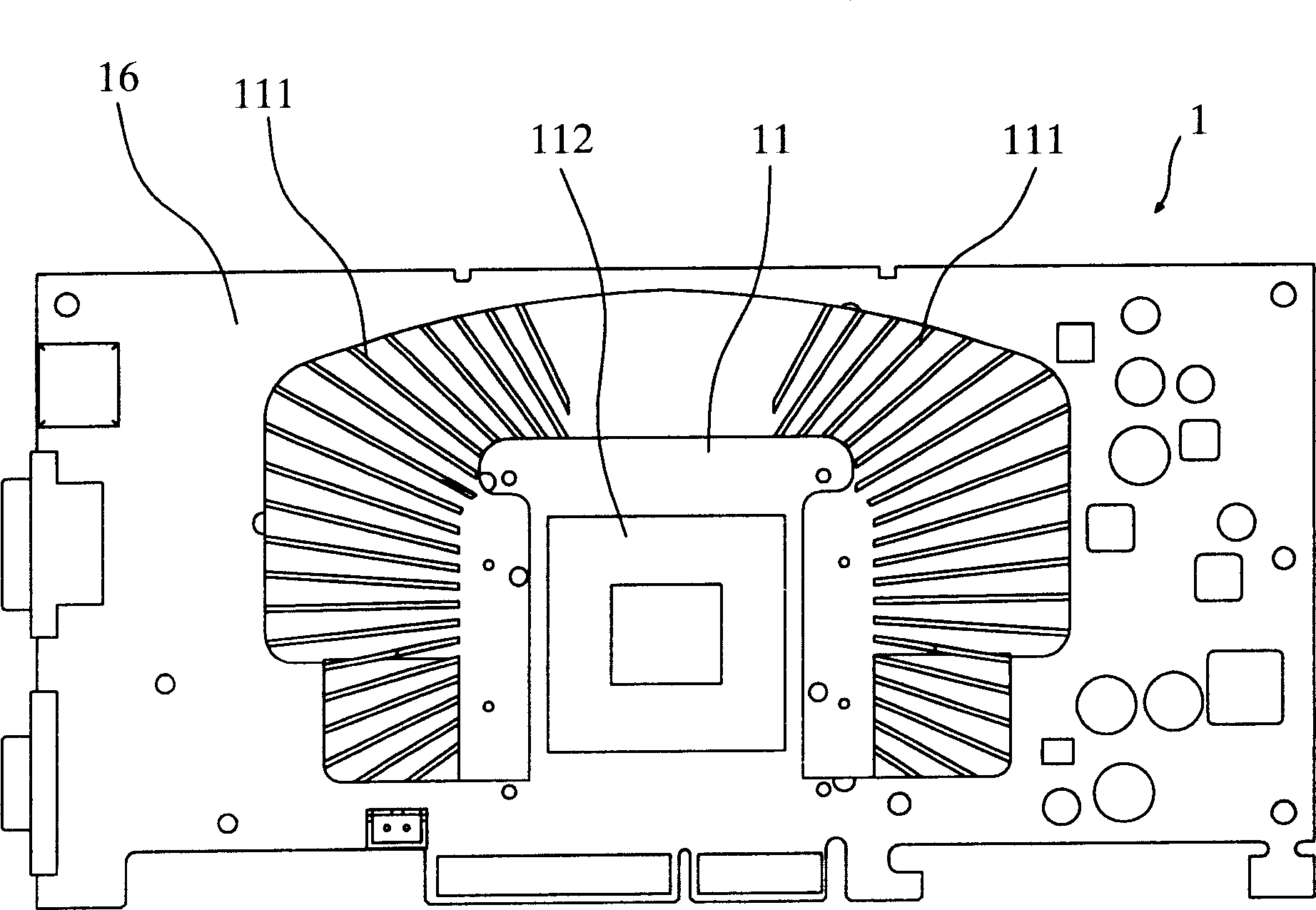
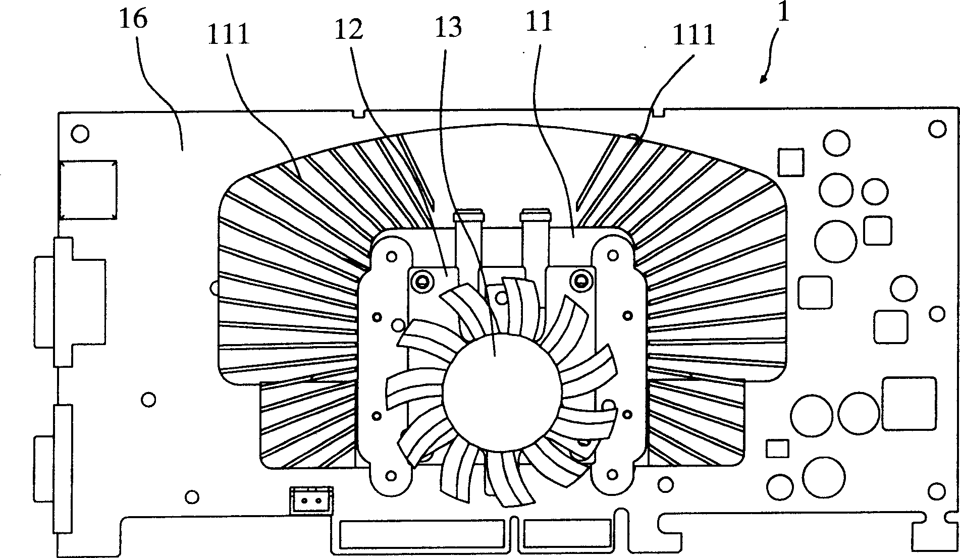
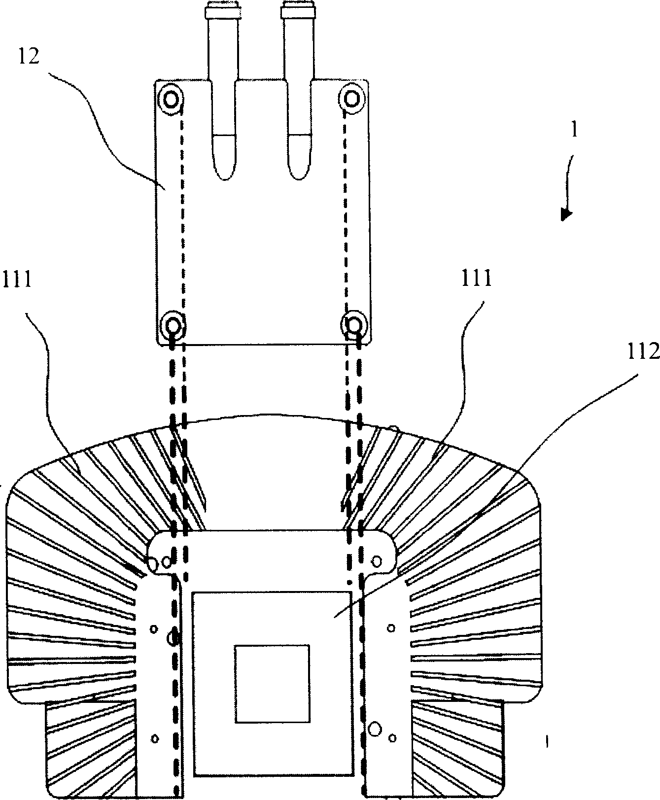
[0036] The present invention is a heat dissipating system, which is used to remove heat energy generated by an electronic component during operation. In particular, the present invention is a dual-mode heat dissipating system. The dual-mode heat dissipating system uses heat exchange, heat conduction, or a combination of both to remove the electronic components generated during operation. heat energy. A fan can also be added to the dual-mode heat dissipation system, so that the fan can provide an airflow to expedite the removal of the heat energy generated by the electronic components during the working process.

[0037] The dual-mode heat dissipation system provided by the present invention is used for heat dissipation of electronic components, such as heat dissipation of a display chip or heat dissipation of a central processing unit. Several preferred specific embodiments and implementation methods of the present invention will be described in detail below.

[0038] see F...


PUM


Abstract

The cooling system in use for electronic module includes a radiator module and a heat exchange module. The radiator module includes a base seat attached to electronic module to transfer heat energy generated by the electronic module. Multiple heat radiating fins are setup around the radiator module. Being fixed on the base seat, the heat exchange module is thermal coupled to the base seat to remove heat energy transferred by the base seat. The cooling system raises efficiency of heat elimination greatly. Even if fault of one part from fan in the cooling system or water-cooled heat sink occurs, electronic module will not be overheated.

Description

technical field [0001] The invention relates to a heat dissipation system, in particular to a dual-mode heat dissipation system for heat dissipation of electronic components. Background technique [0002] Common electronic components, such as central processing units and display chips, need to install at least one cooling device to avoid overheating of these electronic components. If the heat dissipation is not effective, these electronic components may be damaged. The new generation of electronic components Components are running faster and faster, which also means that this new generation of electronic components is running hotter and hotter. Therefore, how to provide an effective heat dissipation mechanism for the above-mentioned electronic components has become a very important issue. [0003] At present, the heat dissipation devices of electronic components are mainly divided into two types. One is to use a high-speed fan to provide an airflow for heat dissipation. A ...

Claims


Application Information

Patent Timeline
IPC IPC(8): H01L23/34G06F1/20H05K7/20
Inventor 林英宇施博仁林志宪
Owner GIGA BYTE TECH CO LTD
Why Eureka
Try Eureka