Control for increasing mixed-kinetic braking-energy recovery of automobile

A technology of braking energy recovery and hybrid electric vehicles, which is applied to hybrid vehicles, motor vehicles, transportation and packaging, etc., which can solve the problems of reducing the fuel economy of the whole vehicle and less recovery of braking energy, so as to improve the fuel economy , The effect of improving the recovery rate

Inactive Publication Date: 2007-01-17
FAW GROUP
View PDF0 Cites 30 Cited by
  • Summary
  • Abstract
  • Description
  • Claims
  • Application Information

AI Technical Summary

Problems solved by technology

like figure 2 As shown, the braking energy recovery

Method used


Image

  • Control for increasing mixed-kinetic braking-energy recovery of automobile
  • Control for increasing mixed-kinetic braking-energy recovery of automobile
  • Control for increasing mixed-kinetic braking-energy recovery of automobile

Examples


Embodiment Construction

[0010] The present invention will be further described below in conjunction with accompanying drawing:

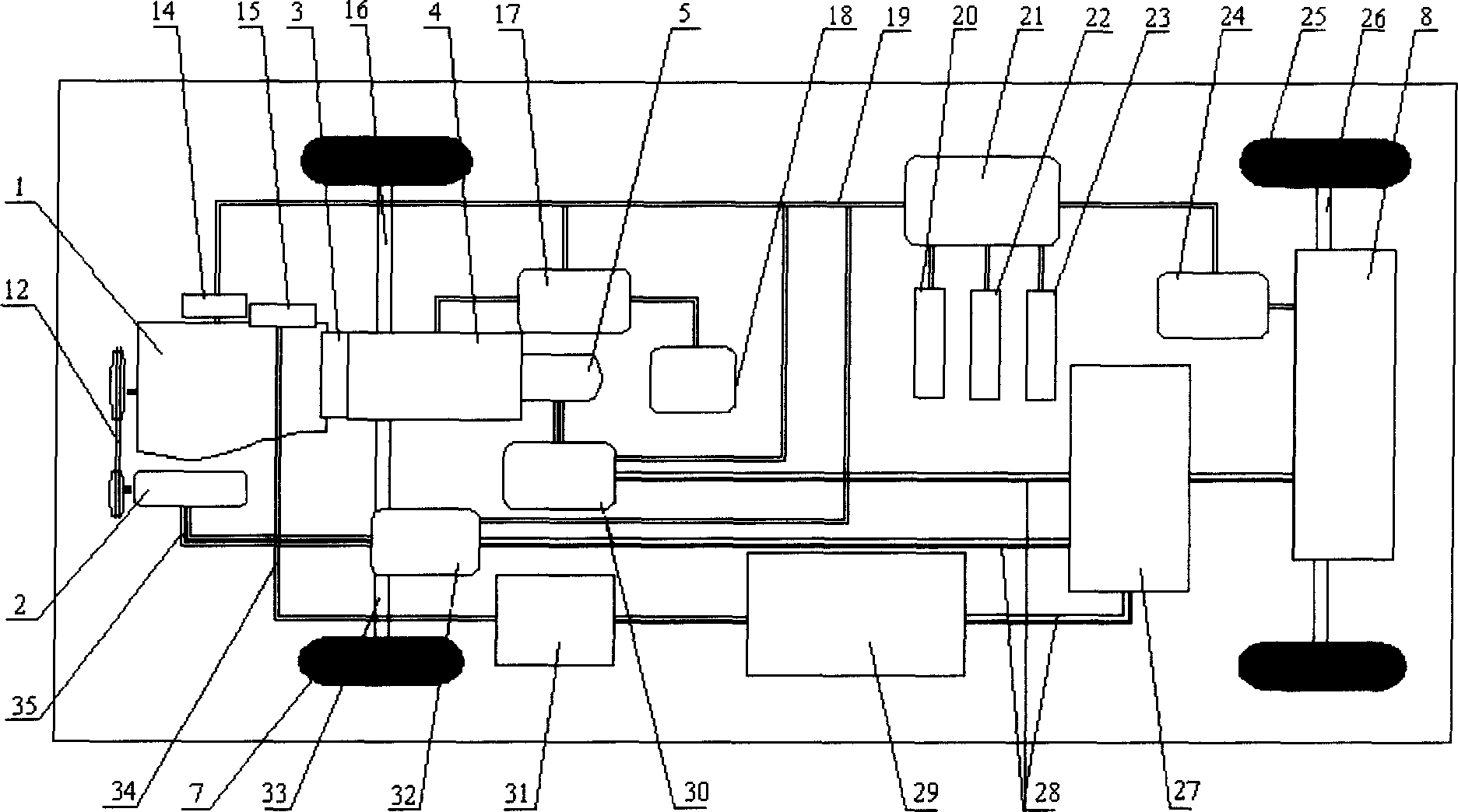
[0011] Such as figure 1 In the hybrid electric vehicle composed of the parallel hybrid system shown, the main motor 5 is arranged at the rear end of the transmission 4 (AMT type, the transmission is integrated with the final drive and the differential), and the rotor shaft of the motor is directly connected to the output shaft of the transmission; The auxiliary motor 2 is arranged on one side of the engine 1, and is connected with the front end of the crankshaft of the engine through a belt. The main / auxiliary motor controller 30 / 32, the engine control unit 14, the controller 17 of the automatic shifting mechanical transmission AMT, the vehicle controller 21, and the battery management unit 24 in the structure are the energy management and automatic control units of the hybrid power system. Electronic devices are required, and they are connected by a network (such as CAB-...


PUM


Abstract

A control method for improving the braking energy recovery of the car with mixed power features that when the car is braked for deceleration, the engine is separated from power drive system by clutch and the electric generation load of electric generator is increase by recovering the braking energy.

Description

Technical field: [0001] The invention relates to a control method for a power system of a hybrid electric vehicle, in particular to a control method for improving braking energy recovery of a hybrid electric vehicle. Background technique: [0002] With the increasingly prominent global environmental and energy issues, the development of new vehicles with low emissions and low fuel consumption has become the primary task of the development of the automotive industry today. Hybrid electric vehicle technology avoids the shortage of battery technology and energy infrastructure of pure electric vehicles. It is a good solution to current problems and has become a hot spot in international automotive research and development. [0003] It is one of the main ways for HEVs to save energy by using electric motors to generate electricity and recover braking energy. At present, in the power system of parallel hybrid electric vehicles, when the vehicle brakes and decelerates, the engine ...

Claims


Application Information

Patent Timeline
IPC IPC(8): B60W10/18B60W10/02B60W10/26B60W20/00B60L7/18B60W10/196B60W20/14B60W20/15
Inventor 唐志强于永坤江国华朱彦文市川耕司吉見秀和松下昌弘龍見哲治伊藤伸一大屋勝則荒川誠
Owner FAW GROUP
Why Eureka
Try Eureka