Supercharge Your Innovation With Domain-Expert AI Agents!

Bracket fixing structure of motor

A technology for fixing structures and brackets, applied in the direction of magnetic circuit shape/style/structure, electrical components, electromechanical devices, etc., can solve the problems of screw corrosion, etc., and achieve a solid bonding state, easy assembly and disassembly process, and high reliability. Effect

Inactive Publication Date: 2010-05-12
TAIZHOU LG ELECTRONICS REFRIGERATOR CO LTD
View PDF2 Cites 0 Cited by
  • Summary
  • Abstract
  • Description
  • Claims
  • Application Information

AI Technical Summary

Problems solved by technology

Therefore, when the motor is used in a place with high humidity, the screws may be corroded by moisture.

Method used


Image

  • Bracket fixing structure of motor
  • Bracket fixing structure of motor
  • Bracket fixing structure of motor

Examples


Embodiment Construction

[0026] The present invention will be described in detail below with reference to the drawings and embodiments.

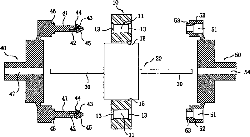
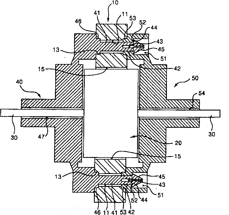
[0027] figure 2 Is an exploded sectional view of the fixing structure of the motor bracket of the present invention, image 3 It is an assembly sectional view of the fixing structure of the motor bracket of the present invention. As shown in the figure, a pair of through holes 11 are formed in the stator 10 of the motor. The through holes 11 are portions where the fixing rods 41 each having both sides of the first bracket 40 will penetrate. Both ends of the through hole 11 are formed with mounting grooves 13 having a relatively larger diameter than the through hole.

[0028] In addition, a rotor hole 15 for inserting the rotor 20 is formed in the stator 10. The rotor 20 rotates with the rotating shaft 30 as the center under the electromagnetic force interaction with the stator 10.

[0029] There are also first and second brackets 40 and 50 for rotatably supporting the...


PUM


Abstract

An electric-motor bracket fixing structure, including: the both sides of the first bracket fixes the flexible fixing pole, forms the fixing hole on both sides of the second bracket at the corresponding position of the fixing pole. The fixing pole is formed by more than one pair of flexible dowels with definite distance at the direction that is vertical to the combining direction of the fixing hole. The fixing pole fixes in the fixing hole at the condition that transfixes the stator transfixing hole, thereby the first bracket and the second bracket are fixed. The invention is: the parts quantity to fixing the first bracket and the second bracket is reduced, that not only decreases the assemble steps, improves the assemble efficiency, but also stops the rust of screw connection and the noiseof the fixing start.

Description

Technical field [0001] The present invention belongs to the field of motors, and particularly relates to a motor bracket fixing structure having first and second brackets that support a rotor to a stator in a rotatable state. Background technique [0002] figure 1 It is an exploded sectional view of the fixing structure of the motor bracket in the prior art. [0003] As shown in the figure, the stator 1 is formed with a pair of through holes 1a through which the screws 6 for fixing the first and second brackets 4 and 5 can penetrate. In addition, a rotor hole 1b for inserting the rotor 2 is formed in the stator 1. The rotor 2 uses the electromagnetic force interaction with the stator 1 in a state of penetrating the rotor hole 1b to rotate around the rotating shaft 3. [0004] In order to support the rotatable state of the rotor 2 in the stator 1, first and second brackets 4 and 5 are provided. The first and second brackets 4, 5 can be made of synthetic resin materials. The first ...

Claims


Application Information

Patent Timeline
Patent Type & Authority Patents(China)
IPC IPC(8): H02K1/18H02K5/04
Inventor 河尚昱
Owner TAIZHOU LG ELECTRONICS REFRIGERATOR CO LTD
Features
  • R&D
  • Intellectual Property
  • Life Sciences
  • Materials
  • Tech Scout
  • Unparalleled Data Quality
  • Higher Quality Content
  • 60% Fewer Hallucinations
Learn More