Light-network 650nm information transmission system

An information transmission system and all-optical network technology, applied in the field of network equipment, can solve the problems of affecting transmission speed, susceptibility to external interference, signal attenuation, etc., and achieve the effect of low comprehensive cost, strong anti-interference ability, and easy interface

Inactive Publication Date: 2007-01-17
江苏华山光电有限公司
View PDF0 Cites 0 Cited by
  • Summary
  • Abstract
  • Description
  • Claims
  • Application Information

AI Technical Summary

Problems solved by technology

[0002] The existing quartz optical fiber network information on the main line must undergo optical/electrical and electrical/optical conversion when it is connected to the user terminal. This

Method used


Image

  • Light-network 650nm information transmission system
  • Light-network 650nm information transmission system
  • Light-network 650nm information transmission system

Examples


Embodiment Construction

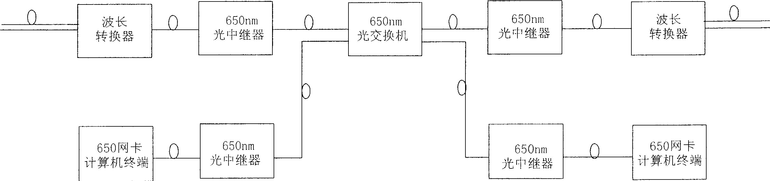
[0031] Such as figure 1 As shown, the 1550nm or 1310nm or 850nm quartz optical fiber signal is converted into a 650nm plastic optical fiber signal wavelength converter, optical repeater, optical switch, optical repeater, and optical network card. The working wavelength of receiving and sending modules is 650nm.

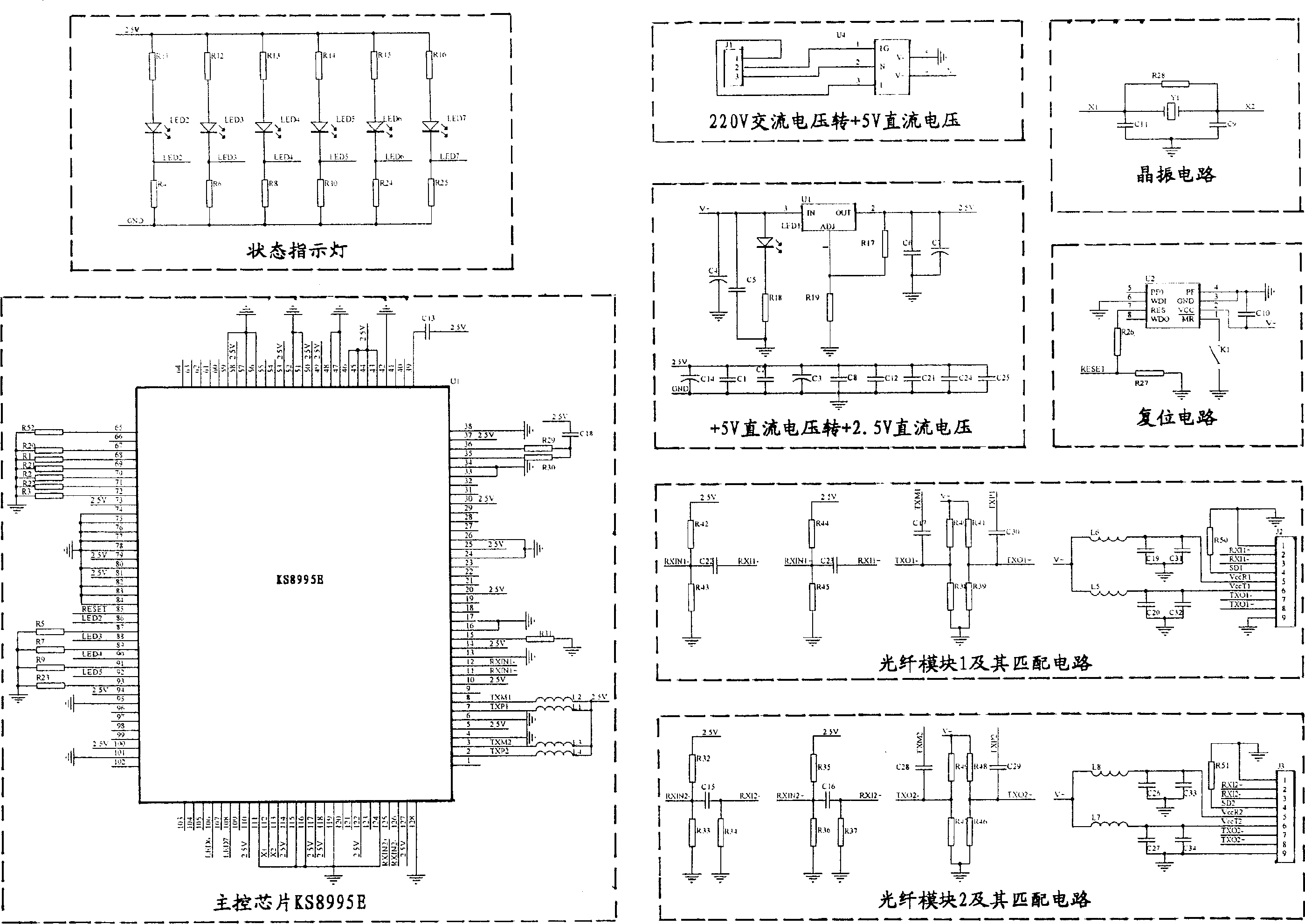
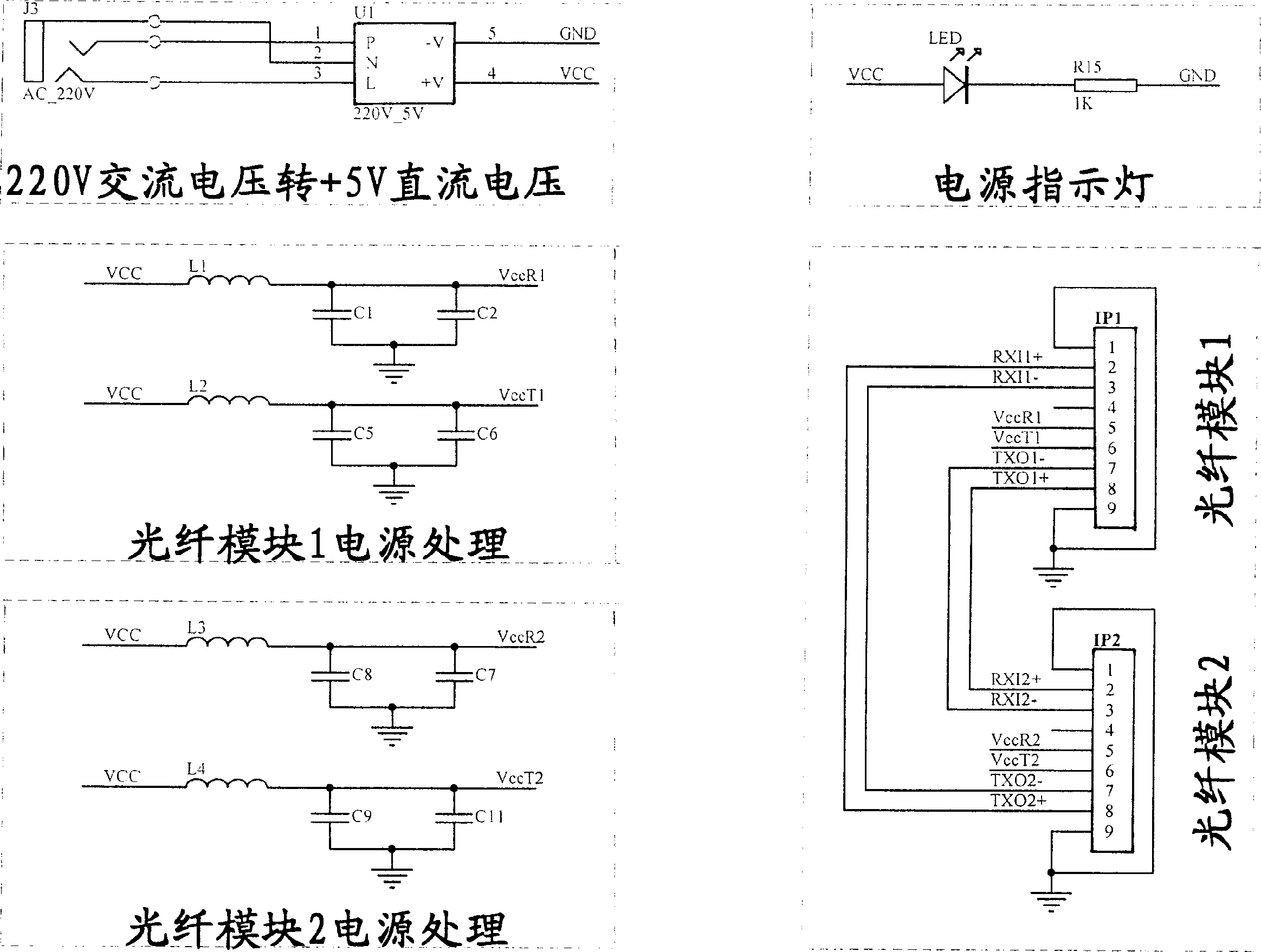
[0032] Such as figure 2 As shown, the wavelength converter is composed of the main control chip KS8995E, optical fiber module and its matching circuit, reset circuit, voltage conversion circuit, status indicator circuit and 25MHz crystal oscillator circuit. The 25MHz crystal oscillator circuit provides the clock source for the main control chip; the voltage conversion circuit includes two parts, namely, 220V AC voltage to +5V DC voltage and +5V DC voltage to +2.5V DC voltage. The former is to enable the system to be directly connected to the mains power system, and the +5V output voltage is used by the reset circuit and optical fiber module; the +2.5V transformed b...


PUM


Abstract

The apparatus comprises a wavelength shifter for shifting the 1551nm or 1310nm or 850nm silicon optical fiber signals into 650nm plastic optical fiber signals, an optical switch and an optical network card. The wavelength shifter, optical switch and optical network card are sequentially connected through a 100Mbps plastic optical transceiver module working at 650nm wavelength.

Description

technical field [0001] The present invention relates to a network device, in particular to a user terminal device of an optical network, which is commonly known as the "last mile" user terminal device. Background technique [0002] The quartz optical fiber network information on the existing main line must undergo optical / electrical and electrical / optical conversion when it is connected to the user terminal. This conversion process not only affects the transmission speed, but also causes signal attenuation, information distortion, and is susceptible to external interference. It is also prone to information theft. Contents of the invention [0003] The purpose of the present invention is to provide a fast, stable and safe all-optical network 650nm information transmission system for end users. [0004] The invention consists of converting 1550nm or 1310nm or 850nm quartz optical fiber signals into 650nm plastic optical fiber signal wavelength converters, optical switches, ...

Claims


Application Information

Patent Timeline
IPC IPC(8): H04B10/12H04B10/25
Inventor 乔桂兰徐蓉艳
Owner 江苏华山光电有限公司
Why Eureka
Try Eureka